
Integrated Punching, Hydraulic Shearing and Bending for Copper and Aluminum Busbars
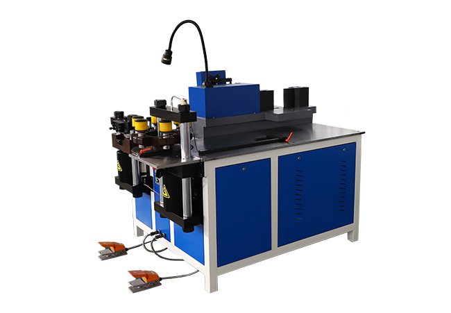
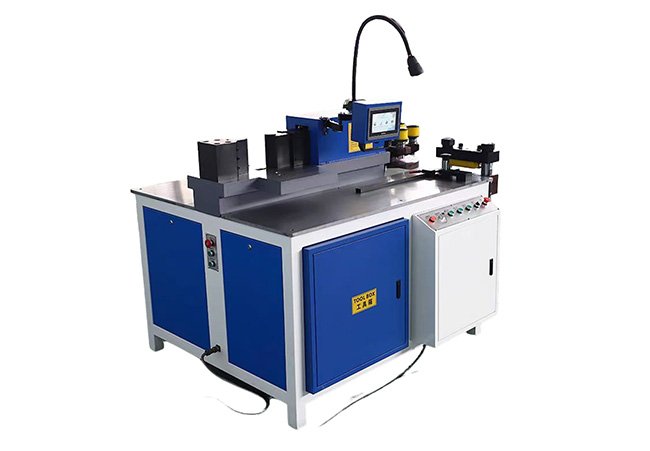
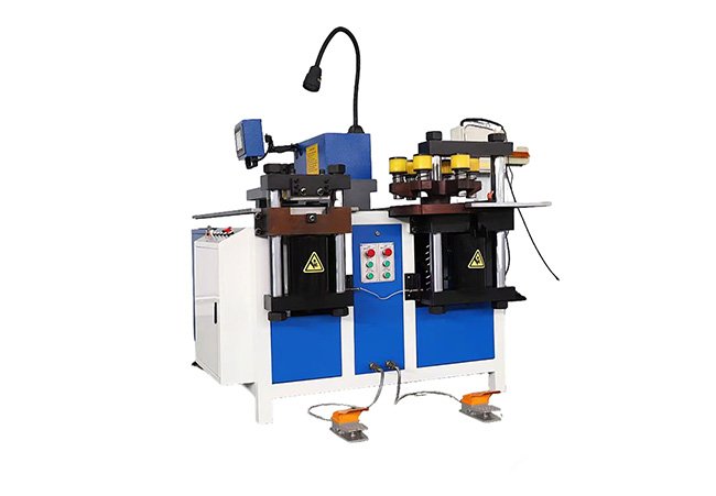
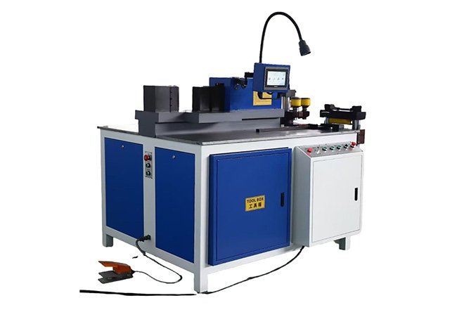
The 500 kN 3-in-1 Busbar Processing Machine is a manually fed, three-station hydraulic machine for punching, hydraulically shearing and bending copper and aluminum busbars. Its stated overall working range is 15–200 mm wide and 3–15 mm thick; actual capacity depends on the material standard and grade, operation, hole diameter, bend geometry and tooling. A PLC touchscreen with digital measurement assistance supports repeatable setup while material loading and longitudinal movement remain manual.
- Processes copper and aluminum busbars within a stated overall range of 15–200 mm in width and 3–15 mm in thickness
- Integrates dedicated punching, hydraulic shearing and bending stations within one machine frame
- Provides a rated force of 500 kN at each station when operated individually
- Supports mixed specifications, customized drawings and small- to medium-batch production
- Supports manually handled workpieces up to 4,000 mm long with suitable external roller supports
- General Specifications
- Punching
- Shearing
- Bending
| Parameter | Value |
|---|---|
| Product Type | 500 kN Hydraulic 3-in-1 Busbar Processing Machine |
| Machine Configuration | Three-Station, Manually Fed Hydraulic Busbar Processor |
| Processing Functions | Punching / Hydraulic Shearing / Bending |
| Processing Material | Copper Busbar / Aluminum Busbar |
| Overall Busbar Width Range | 15–200 mm |
| Overall Busbar Thickness Range | 3–15 mm |
| Recommended Workpiece Length | Up to 4,000 mm with Suitable External Roller Support |
| Material Feeding Method | Manual Feeding |
| Measurement Method | PLC-Assisted Digital Measurement |
| Control Interface | PLC Touchscreen |
| Hydraulic System Pressure | 31.5 MPa |
| Total Installed Power | 10–12 kW, Depending on Hydraulic and Electrical Configuration |
| Power Supply | 380 V / 50 Hz / 3 Phase |
| Machine Dimensions | Approximately 1,700 × 1,700 × 1,600 mm |
| Machine Net Weight | Approximately 2,100 kg |
| Parameter | Value |
|---|---|
| Maximum Punching Force | 500 kN |
| Punching Method | Hydraulic Punching Unit |
| Round-Hole Diameter Range | Ø4.3–Ø35 mm |
| Standard Hole Type | Round Hole |
| Optional Hole Types | Subject to Available Punch-and-Die Configuration |
| Material Positioning | Manual Positioning with Digital Measurement Reference |
| Standard Tooling | Confirmed Punch-and-Die Sizes Supplied with Final Configuration |
| Parameter | Value |
|---|---|
| Maximum Shearing Force | 500 kN |
| Shearing Method | Hydraulic Shearing Unit |
| Material Positioning | Manual Positioning |
| Applicable Materials | Copper and Aluminum Busbars |
| Maximum Shearing Capacity | Confirmed According to Material Grade, Thickness and Blade Configuration |
| Workpiece Support | External Roller Support Recommended for Long Busbars |
| Parameter | Value |
|---|---|
| Maximum Bending Force | 500 kN |
| Bending Method | Hydraulic Bending Unit |
| Nominal Finished-Angle Range | 0–90° |
| Standard Bending Type | Flat Bending |
| Vertical Bending | Subject to Tooling and Machine Configuration |
| Material Positioning | Manual Positioning |
| Minimum Bending Radius | Confirmed According to Material, Thickness and Tooling |
| Finished Bending Result | Depends on Material Grade, Tooling Radius, Geometry and Springback |
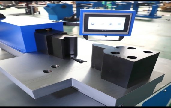
PLC-Assisted Digital Measurement for Manual Positioning
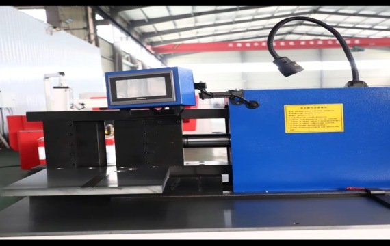
Operators enter the required dimension through the PLC touchscreen. The digital measuring system provides a positioning reference for punching, shearing or bending setup. The operator then manually adjusts the stop, advances the busbar and confirms alignment before activating the selected processing station. Material feeding and longitudinal positioning are not servo-controlled. This operating method reduces repeated manual marking while retaining flexibility for mixed specifications and customized components.
31.5 MPa Hydraulic System and Sequential Station Operation
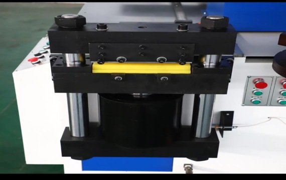
A hydraulic system rated at 31.5 MPa powers the dedicated punching, shearing and bending stations. Each station provides a rated force of 500 kN when operated individually. The punching station applies hydraulic force through the selected punch-and-die set. The shearing station uses a dedicated hydraulic blade assembly, while the bending station applies force through the selected bending tooling. The standard configuration is designed for sequential station operation. If simultaneous operation is required, it must be evaluated as a separate hydraulic and electrical configuration before ordering.
Who Is This 500 kN Machine Designed For?
The machine is intended for manufacturers of switchgear, transformers, electrical panels and busbar assemblies that handle mixed specifications, customized drawings and small- to medium-batch production. Manual material movement provides flexibility when dimensions change frequently. An automatic punching-and-shearing line is generally more suitable for long repetitive batches requiring servo feeding, nesting, drawing import or unattended cycles.
- Switchgear manufacturers
- Transformer manufacturers
- Electrical-panel manufacturers
- Busbar assembly workshops
- Power-equipment manufacturers
- Contract busbar fabricators
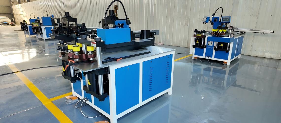
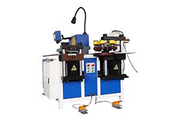
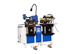
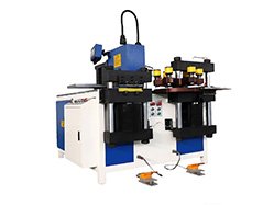
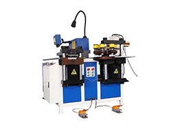
The machine combines hydraulic punching, shearing, and bending within one three-station frame. Operators manually reposition the busbar at the required station for each operation.
It is designed for copper and aluminum busbars. Final processing capacity depends on the material grade, temper, thickness, operation type, tooling, and part geometry.
No. Material loading, longitudinal movement, stop adjustment, and workpiece alignment are manual. The PLC-assisted digital measuring system provides a positioning reference but does not automatically feed the busbar.
Operators enter the target dimension through the PLC touchscreen. The system provides a digital reference, while the operator manually adjusts the stop, advances the busbar, and confirms alignment before activating the selected station.
The standard configuration is designed for sequential station operation. If simultaneous station operation is required, the hydraulic and electrical configuration must be evaluated separately before ordering.

