
Quick Answer
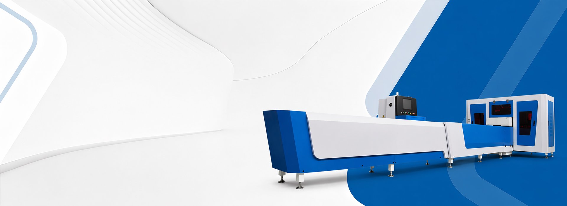
A hydraulic busbar punching machine uses hydraulic force and matched punches and dies to produce holes or slots in copper and aluminum busbars.
The hydraulic system provides the punching force, while hole positioning may be completed manually, with mechanical stops, through digital measurement or by a CNC-controlled feeding system.
Hydraulic pressure alone does not confirm finished-hole accuracy. Select the machine according to the material, width × thickness, hole geometry, edge distance, tooling reach, positioning method, workpiece support and FAT criteria.
What Is a Hydraulic Busbar Punching Machine?
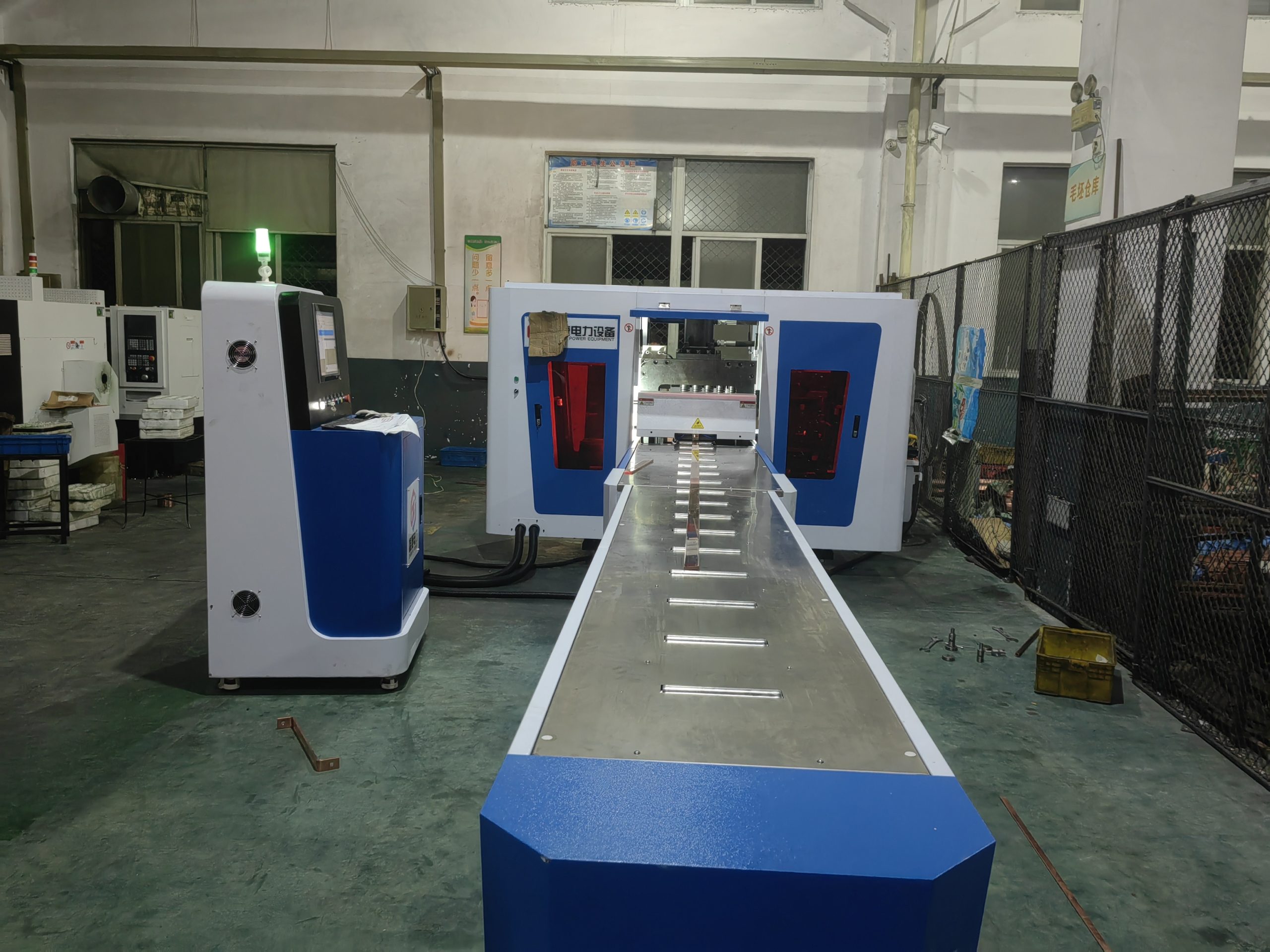
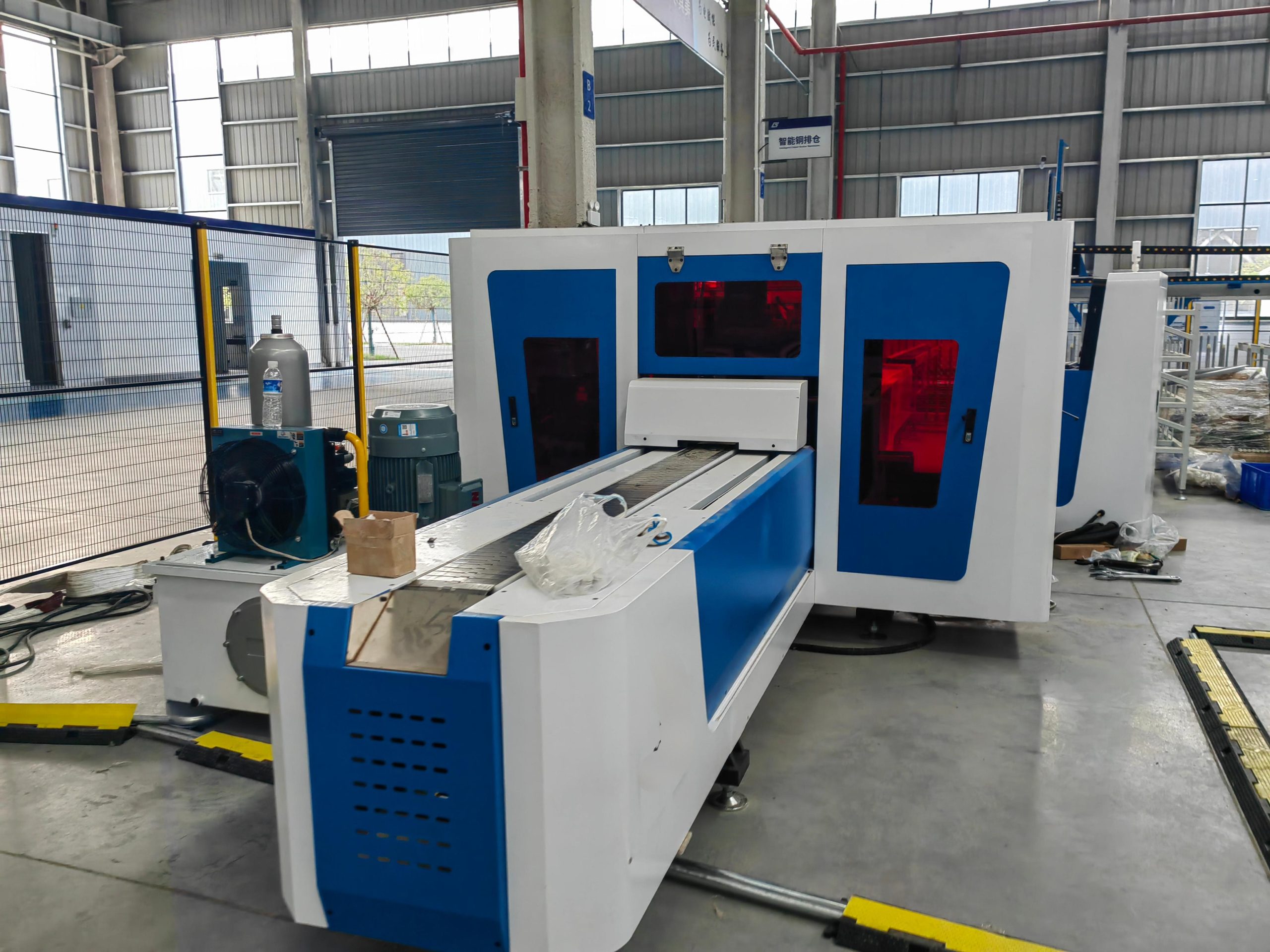
A hydraulic busbar punching machine uses a hydraulic cylinder and matched tooling to produce connection holes, mounting holes and slots in conductive busbars.
The workpiece may be positioned manually, through an adjustable stop, with digital measurement or by a separately specified controlled system. The technical quotation should identify the exact positioning method rather than using the term CNC for every hydraulic machine.
Punching capability depends on the material, thickness, hole dimensions, punch-and-die clearance, edge distance, tooling reach and available force.
The machine name or nominal pressure does not independently confirm finished-hole position, burr condition, deformation or production output. These results should be verified using representative material and drawings.
Fenghua Hydraulic Busbar Punching Machine Solutions
Suitable for customized parts and lower-volume punching where the operator positions the busbar from an approved drawing or marked reference. Confirm the tooling, worktable, throat reach and inspection method.
Uses an adjustable mechanical or digital reference to support recurring hole positions. Confirm the stop range, datum, adjustment procedure and first-part inspection requirements.
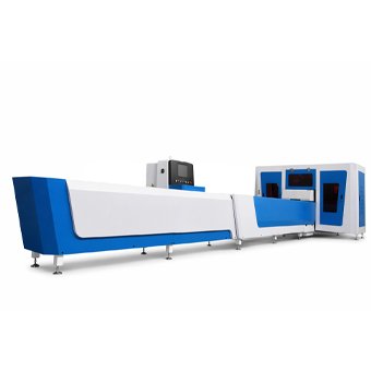
Reviewed for projects using several round, slotted or drawing-specific hole tools. Confirm the included dies, changeover procedure, die storage and replacement-tool lead time.
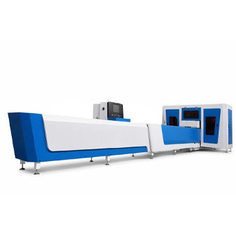
Configured for special hole patterns, longer workpieces, non-standard tooling, material-support devices or workshop-specific operating requirements.
Functions to Confirm Before Selecting a Hydraulic Busbar Punching Machine

Confirm the nominal punching force, applicable copper or aluminum material, maximum thickness for each hole size, hydraulic working pressure and required safety margin.

Confirm the supported round and slotted-hole dimensions, punch-and-die clearance, included tools, non-standard tooling availability, die-change procedure and replacement-tool lead time.

Confirm the drawing datum, manual or assisted positioning method, mechanical-stop range, throat depth, effective tooling reach and whether the workpiece requires repositioning.

Confirm the worktable, long-busbar support, material alignment, operator position, guarding, emergency stop and safe tooling-change procedure.
How Should Hydraulic Punching Output Be Compared?
Do not compare hydraulic punching machines only by cylinder stroke time or nominal punching frequency.
Complete cycle time should include material loading, drawing review or marking, positioning, die selection, punching, workpiece repositioning, unloading and finished-part inspection.
For a fair supplier comparison, use the same material and hole drawing. Record the number of operators, setup time, die-change time, complete cycle time, conforming parts, rejected parts and manual corrections.
Does Hydraulic Pressure Determine Hole Position?
Hydraulic force determines whether the selected punch can penetrate the approved material under the specified tooling conditions.
Hole position is primarily controlled by the drawing datum, positioning method, mechanical stop or feeding system, workpiece alignment and material support.
Finished-hole quality also depends on the material condition, punch-and-die clearance, tool wear, hole geometry, edge distance and workpiece movement.
For this reason, punching force, positioning accuracy, finished-hole accuracy and repeatability should be listed as separate technical and FAT items.
| Check | What to Verify |
|---|---|
| Punching Capacity | Material, thickness, hole size and tooling |
| Hole Position | Measurement from the approved drawing datum |
| Hole Geometry | Diameter, slot length and slot width |
| Edge Quality | Burr, deformation and surface marks |
| Repeatability | Consecutive finished parts |
Where Is a Hydraulic Busbar Punching Machine a Good Fit?
Hydraulic busbar punching machines are commonly reviewed for workshops producing customized or mixed-batch copper and aluminum busbar parts.
They are particularly relevant when hole specifications change regularly, production volumes do not justify a complete automatic line, and manual or assisted positioning is acceptable.
For long repetitive production with recurring coordinates, automatic feeding, nesting or production-data requirements, compare a CNC busbar punching machine or punching-and-shearing line before making the final selection.
The correct configuration should be selected from the actual material, hole drawing, batch mix, operator involvement and complete cycle time rather than the application name alone.
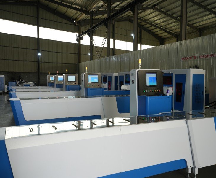
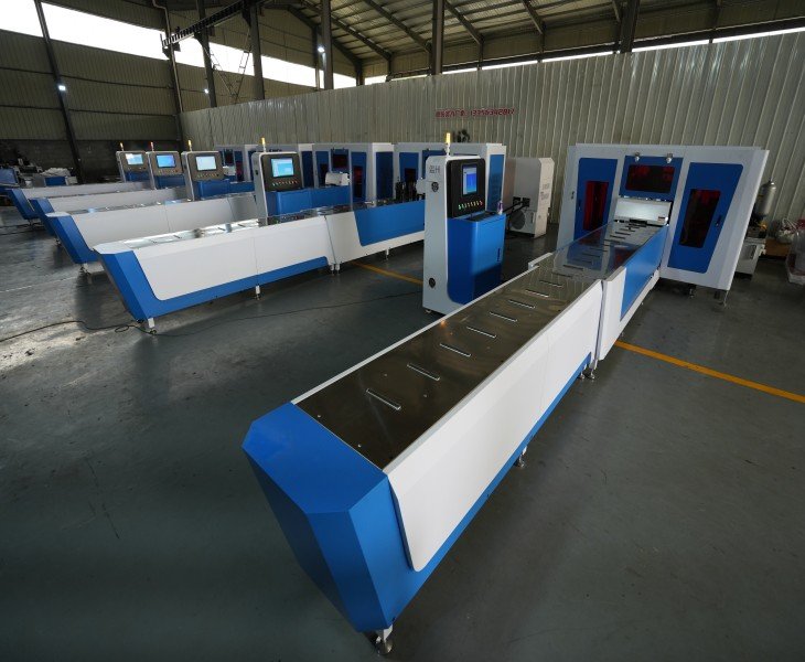
Boost Delivery Speed Of Hydraulic Copper Busbar Punching
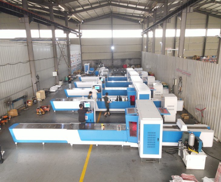
The punching cycle time includes material preparation, mold changes, and hole position adjustments, increasing your delivery pressure. Fenghua hydraulic punching equipment is used in the copper busbar processing stage to help you reduce waiting time and make production plans easier to execute. Your urgent orders for different specifications of copper busbars will thereby reduce equipment idle time and increase productivity. Your workshop processing status is clearer, order progress is smoother, is more controllable.
| Check | What to Verify |
|---|---|
| Punching Capacity | Material, thickness, hole size and tooling |
| Hole Position | Measurement from the approved drawing datum |
| Hole Geometry | Diameter, slot length and slot width |
| Edge Quality | Burr, deformation and surface marks |
| Repeatability | Consecutive finished parts |
Why Do Throat Depth and Edge Distance Matter?
A punching machine must be able to position the required hole under the punch without interference from the machine frame, tooling or workpiece-support system.
Confirm the hole-to-edge distance, hole-center pitch, throat depth, tooling reach and the largest distance from the drawing datum to the required hole.
For wide parts, offset holes or complex patterns, request a drawing review before approving the machine. A machine may have sufficient punching force but still be unable to reach every required hole position.
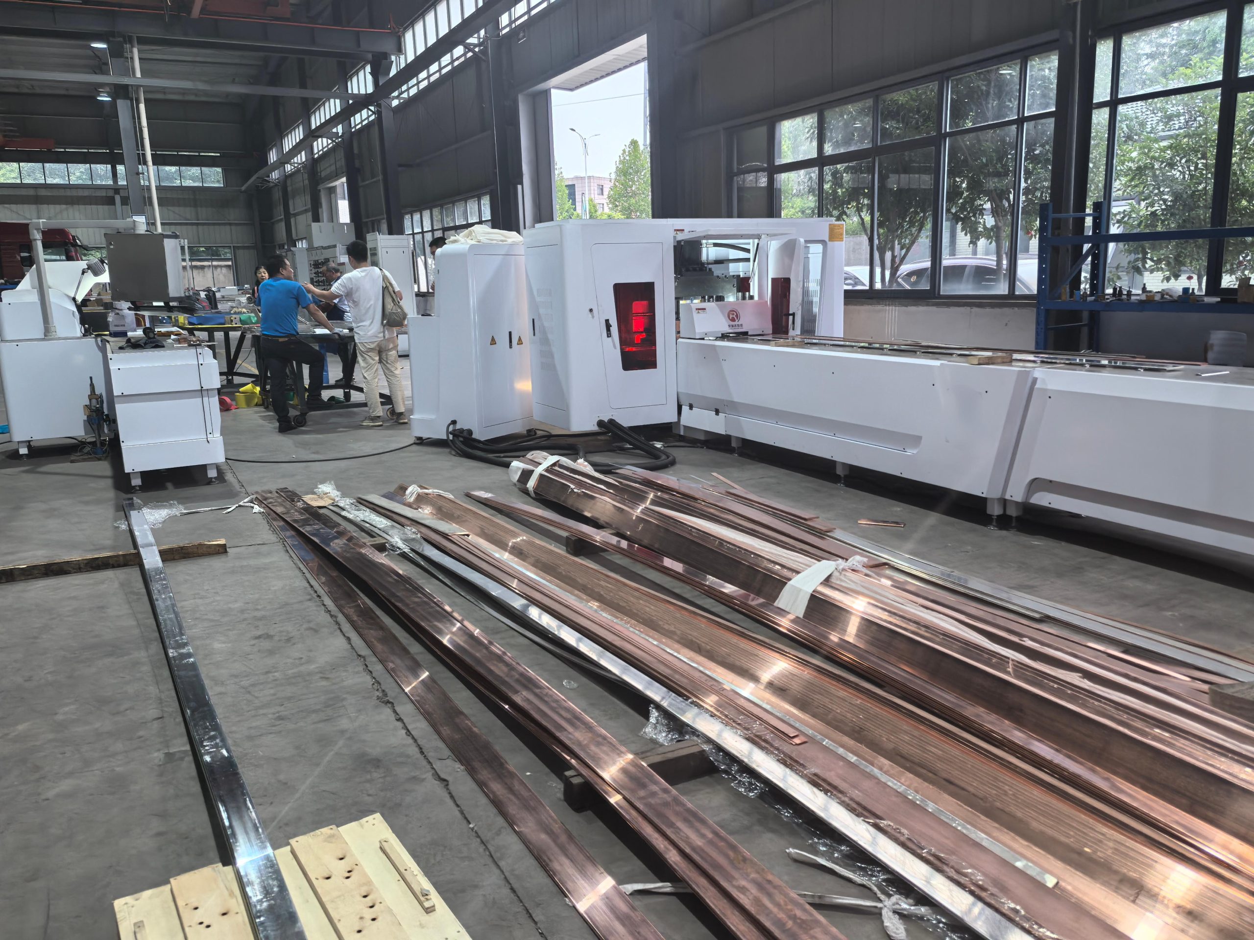
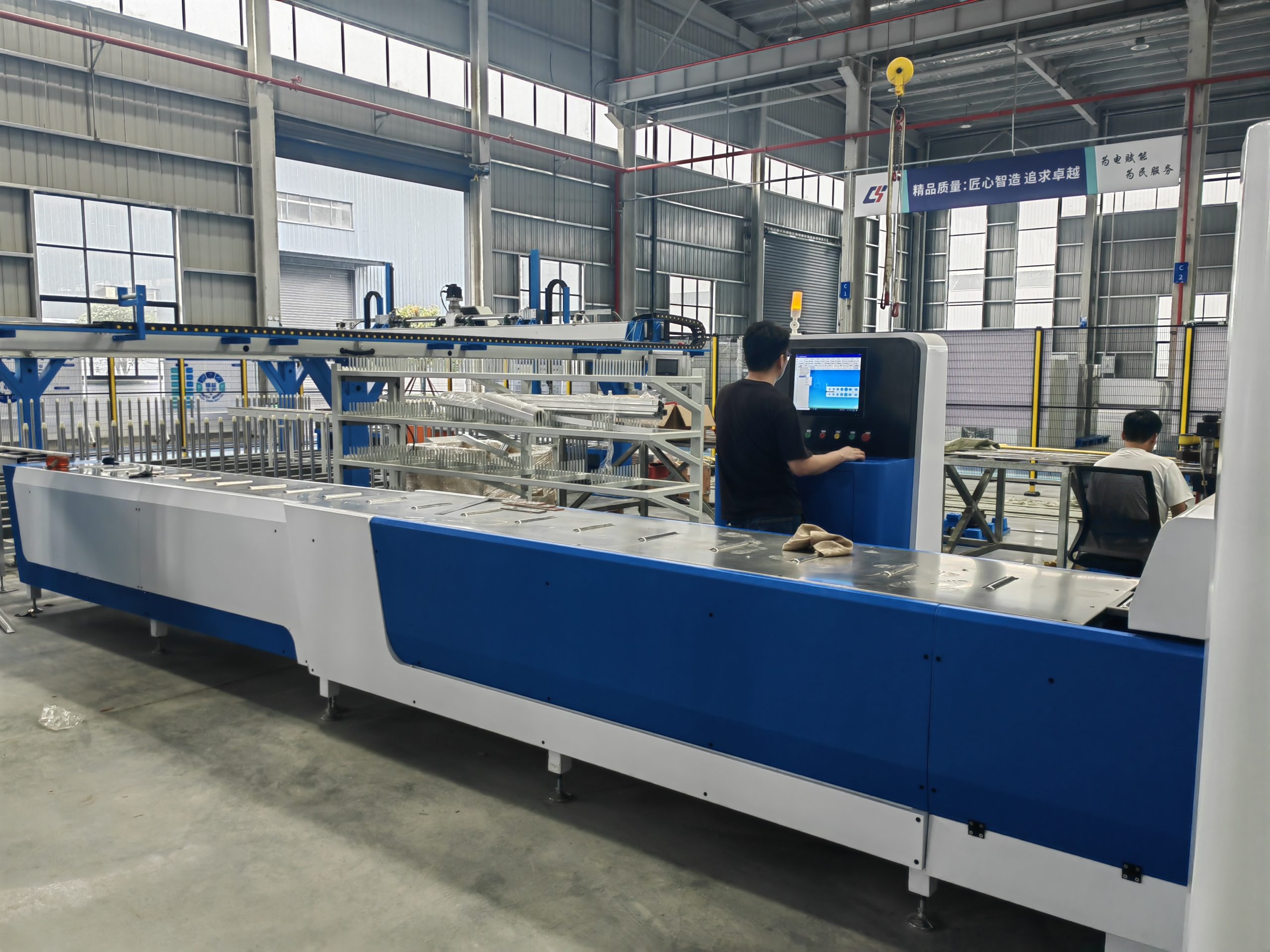
Managing Different Busbar Hole Specifications
Producing different busbar parts may require changes to the punch and die, positioning stop, worktable support, drawing datum and operating settings.
The technical quotation should identify the supported material and hole range, included tooling, changeover procedure and first-part inspection method.
For mixed-specification production, include a practical changeover test during FAT to verify the adjustment steps, setup time and finished-part results.
How to Compare China’s Top 10 Busbar Machine Manufacturers for Hydraulic Punching
There is no universally recognized official ranking of China’s top 10 busbar machine manufacturers. Published lists should be used only to create an initial supplier shortlist.
For a hydraulic punching project, compare the exact machine proposed for your material, hole drawings and production method rather than relying only on company size, nominal force or promotional rankings.
| Comparison Factor | What to Confirm | Evidence to Request |
|---|---|---|
| Exact Configuration | Hydraulic, CNC or punching-shearing machine | Model, layout and nameplate |
| Punching Capability | Material, thickness, hole range and reach | Signed capacity table and samples |
| Positioning and Tooling | Manual, stop-assisted or controlled; included dies | Tooling list and demonstration |
| FAT and Service | Samples, criteria, warranty and spare parts | Signed FAT and service scope |
For a broader sourcing shortlist, review our guide to 10 Busbar Machine Manufacturers in China. The guide is published by FengHua and should not be treated as an official ranking or independent certification.
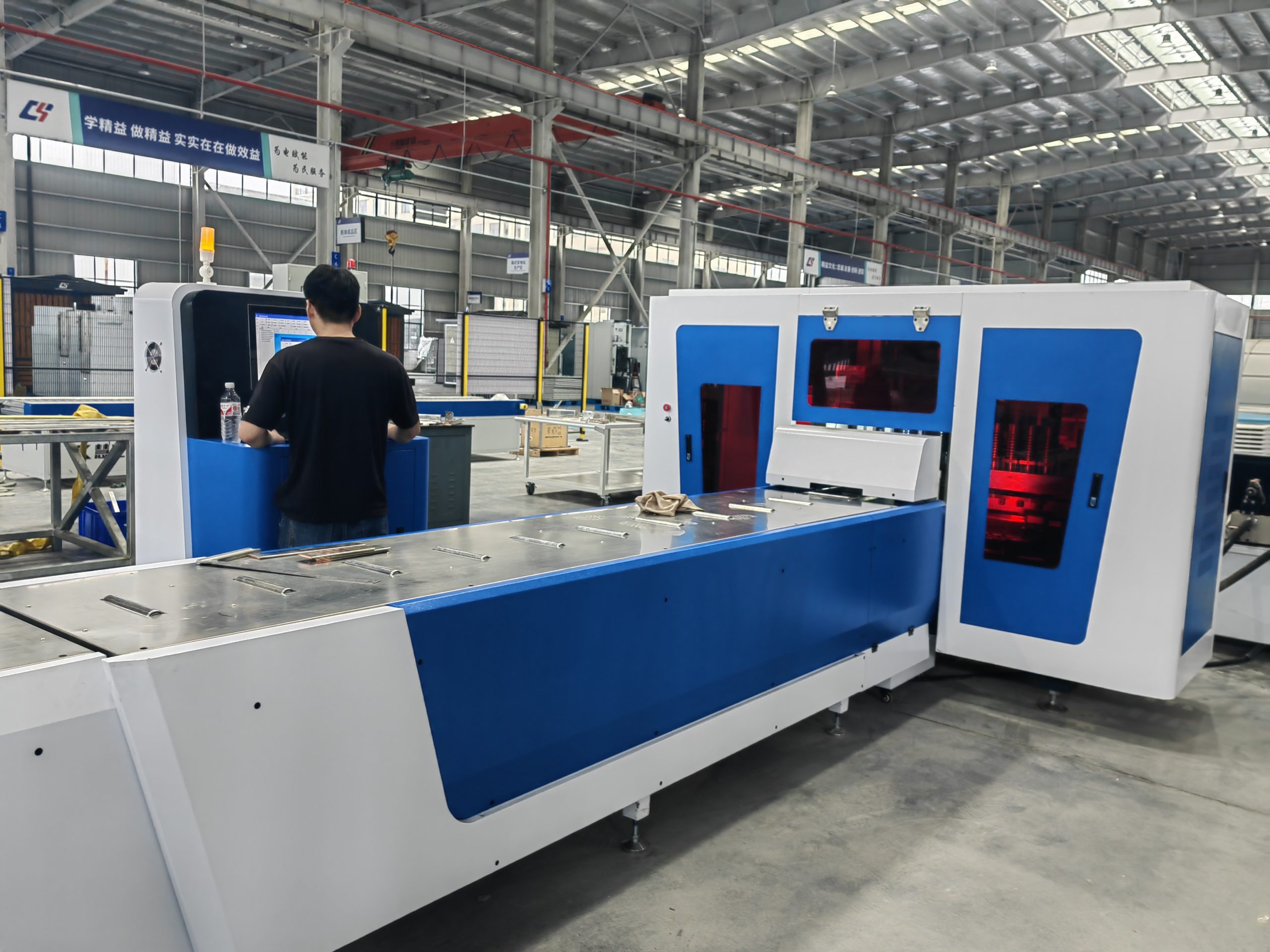
A hydraulic busbar punching machine uses hydraulic force and matched punches and dies to produce holes or slots in copper and aluminum busbars.
Hydraulic describes the punching-force system. CNC describes programmable positioning or control. A CNC punching machine may still use a hydraulic punching unit.
Supported shapes may include round holes, slotted holes and drawing-specific profiles, subject to the approved material, thickness, tooling and edge-distance requirements.
Confirm the material, thickness, hole size, hole shape, edge distance and punch-and-die configuration. Nominal force alone does not prove every hole can be produced through the maximum material thickness.
No. Hydraulic pressure provides punching force. Hole position depends on the drawing datum, positioning method, workpiece alignment and material support.
A CNC configuration may be more suitable for recurring coordinates, longer production runs, program storage, servo feeding or production-data requirements.
Provide the material, width × thickness, raw length, hole and slot drawing, edge distance, positioning preference, batch quantity, output, voltage and FAT requirements.
Use representative material and drawings to verify punching capacity, hole position, geometry, edge quality, tooling change, safety, documents and spare parts against the agreed FAT criteria.
Related Products
- Stable Busbar Punching Machine
- Customized Busbar Punching Machine
- Copper Busbar Punching Machine

