Quick Answer
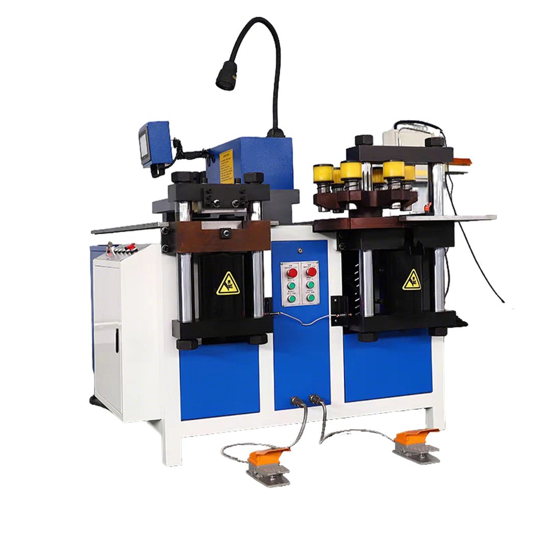
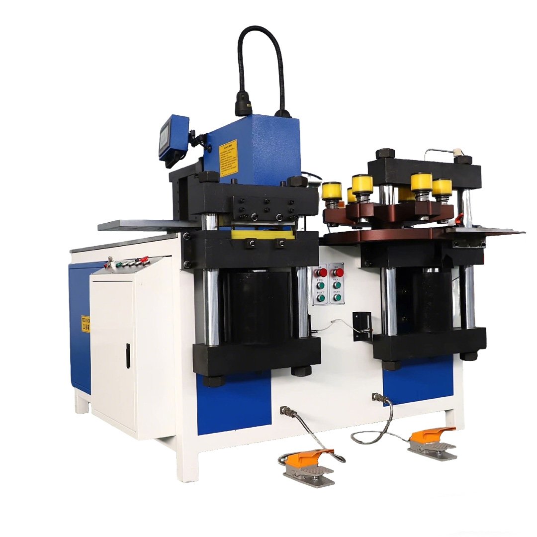
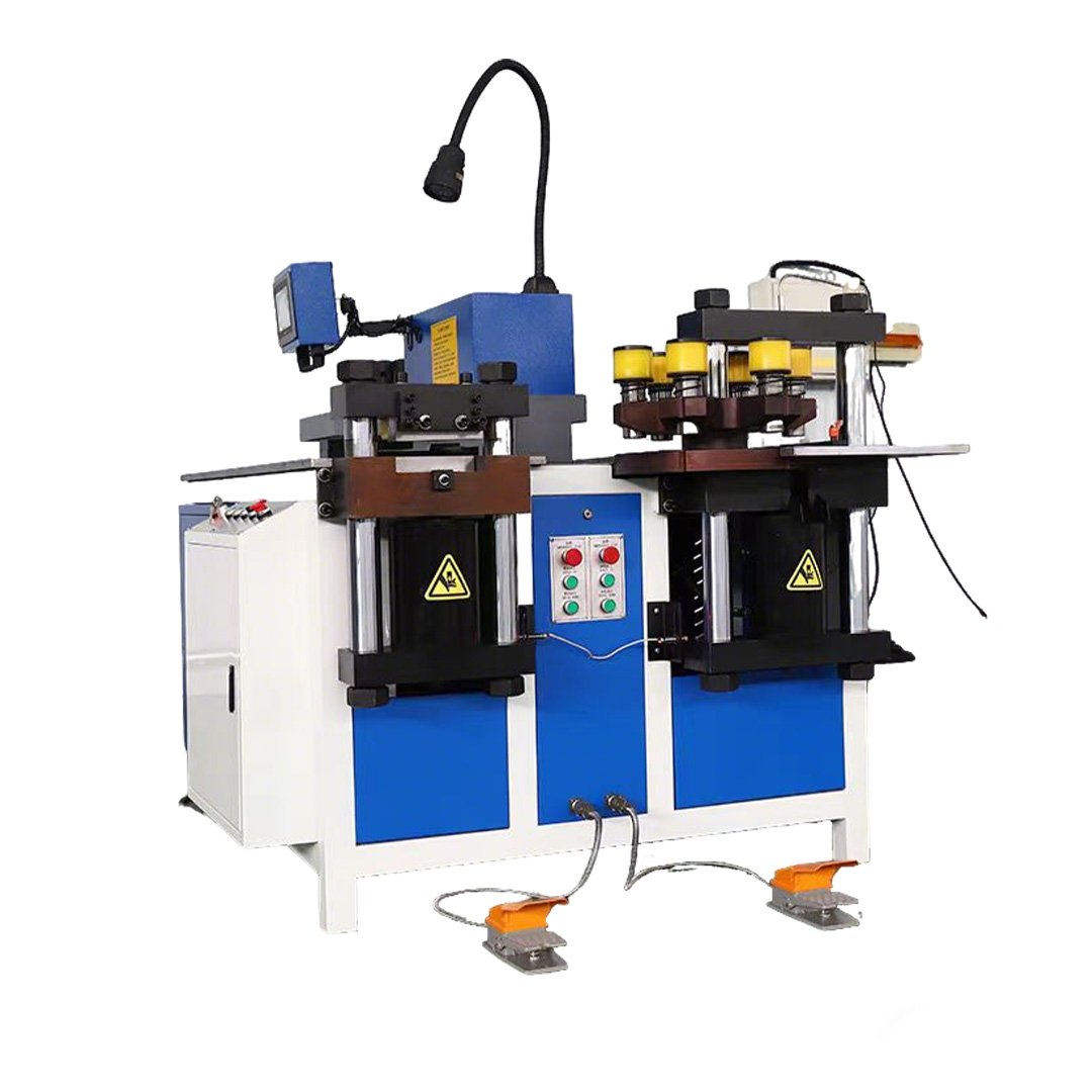
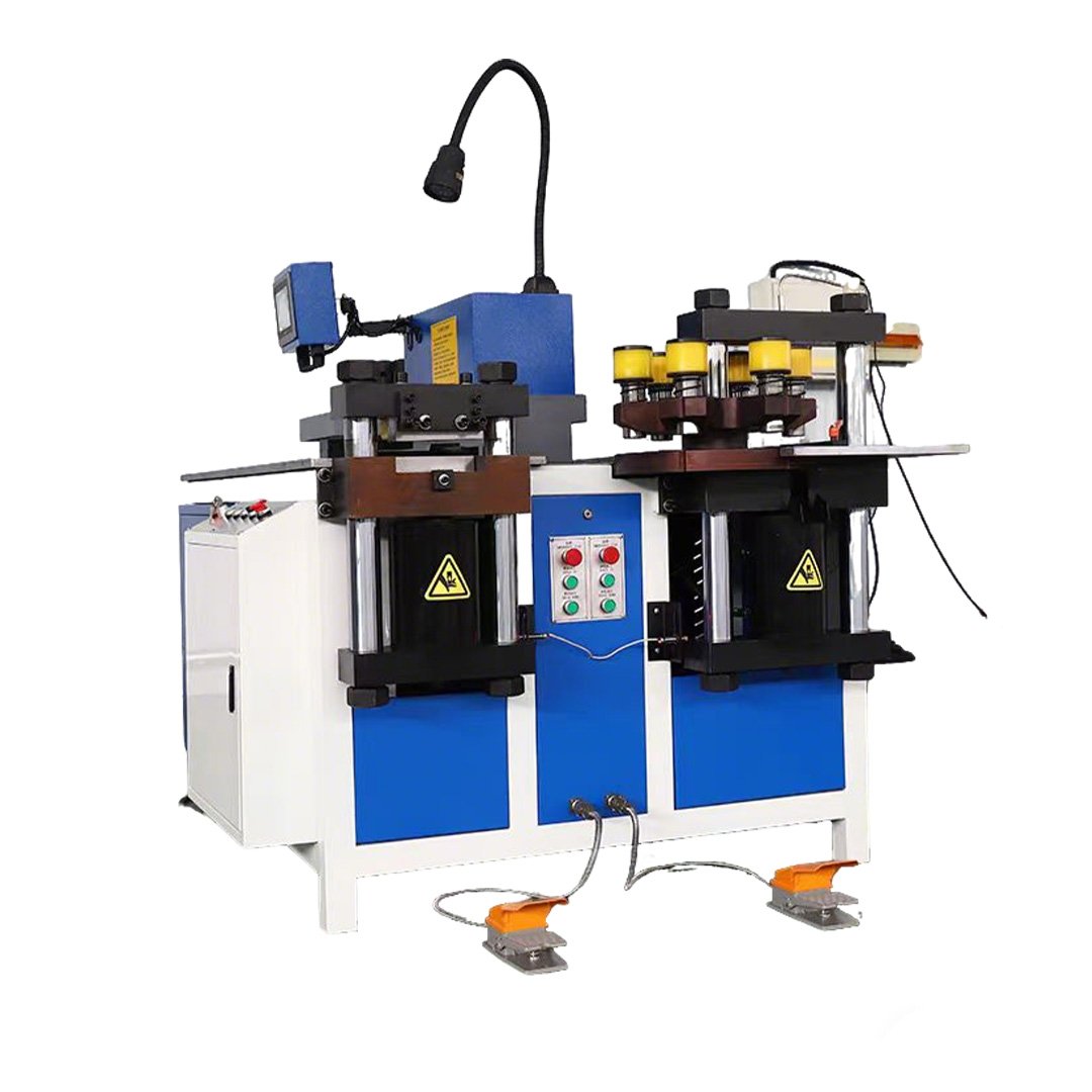
A copper busbar fabrication system may use one integrated 3-in-1 machine or a combination of dedicated punching, shearing and bending equipment.
Start with the approved finished-part drawing and define the material, datums, hole and slot positions, finished length, bend lines, radii, short legs and assembly interfaces. The process sequence should preserve measurable references while avoiding tooling interference, deformation and unnecessary handling.
Confirm punching, shearing and bending capacity separately. Nominal force or an overall maximum busbar size does not prove that every operation can process the maximum material under every tooling and geometry condition.
Select the production route according to complete cycle time, tooling, positioning, workpiece handling, first-part inspection and representative-part FAT evidence.
How Is a Copper Busbar Fabrication System Configured?
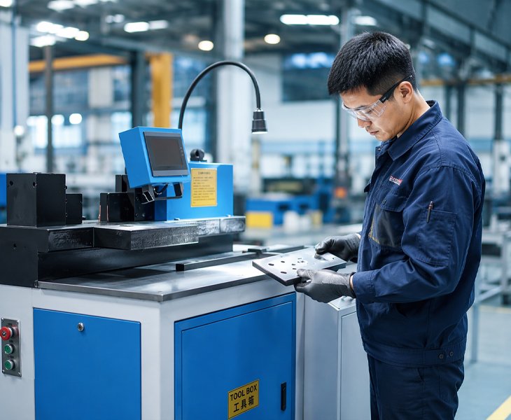
A copper busbar fabrication system is configured from the finished-part drawing rather than selected only by machine force or catalogue capacity.
The production route may use an integrated punching, shearing and bending machine, or separate machines for recurring punching, cutting and forming operations. The correct arrangement depends on the part mix, process sequence, required output, workpiece length, positioning method, tooling access and workshop layout.
The technical quotation should define the exact machine or machines, capacity of each operation, manual and controlled functions, included tooling, material-support requirements, electrical configuration, FAT samples, documentation, warranty and spare-parts scope.
Before quotation, submit representative drawings for parts with the largest material size, smallest edge distance, most complex slot, shortest bend leg and most difficult processing sequence.
Copper Busbar Fabrication Machine Configurations
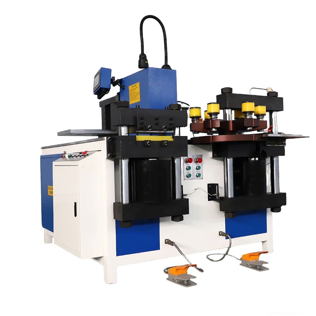
Combines punching, hydraulic shearing and bending stations within one machine frame. Confirm the capacity, tooling and positioning method of each station separately.
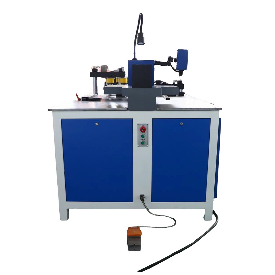
Suitable for recurring hole layouts and fixed-length copper busbar parts. Confirm the controlled axes, feeding range, clamp system, gripper dead zone, minimum part length and cutting requirements.
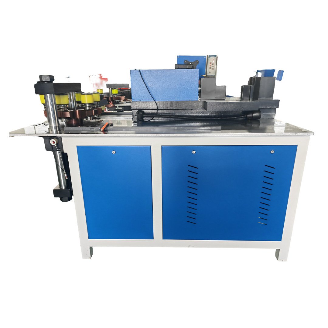
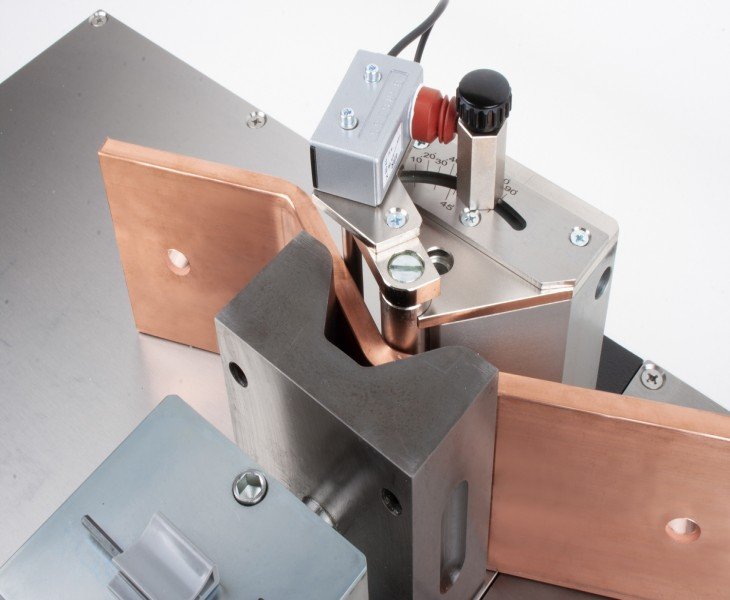
Used for parts requiring controlled flat, vertical or drawing-specific bending. Confirm the material, inside radius, minimum short leg, bend direction, springback and tooling clearance.
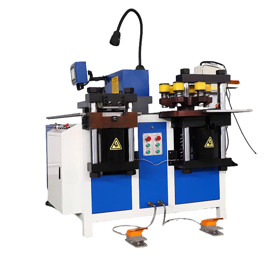
Combines integrated or dedicated equipment according to the part family, process sequence, operator requirements, workshop space and required output.
Functions to Confirm in a Copper Busbar Fabrication System

Confirm the copper grade and temper, material thickness, round and slotted-hole dimensions, punch-and-die clearance, minimum edge distance, hole-center pitch, tooling reach and included die list.

Confirm the applicable width × thickness, blade configuration, cutting datum, finished-length tolerance, cut squareness, burr limit, edge deformation and surface condition.

Confirm flat or vertical bending capability, bend direction, inside radius, minimum short-leg length, tooling clearance, springback adjustment and released-angle acceptance.

Confirm whether measurement, feeding, longitudinal movement, stop adjustment, workpiece rotation and final alignment are manual, digitally assisted, servo-controlled or automatic.
Managing Different Copper Busbar Parts
Producing different copper busbar parts may require changes to the punch and die, shearing reference, bending tool, mechanical stop, positioning program, workpiece support and operating parameters.
The technical quotation should identify the supported material range, supplied tooling, changeover procedure, setup responsibilities and first-part inspection method.
For mixed-specification production, include a practical changeover test during FAT. Record the adjustment steps, setup time, operator involvement, first-part result and any tooling changes.
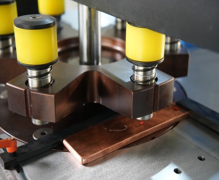
Copper Busbar Fabrication Applications
Switchgear and Electrical Panels
Review the hole layout, finished length, bend structure, assembly datum and cabinet clearances for copper busbars used in switchgear and electrical panels.
Transformer Connections
Confirm the conductor section, terminal-hole geometry, bend direction, surface condition and assembly interface for transformer connection busbars.
Busduct and Busbar Systems
Longer conductors may require dedicated punching, shearing, straightening or material-support equipment. Confirm workpiece length, joint geometry and production volume before selecting the line.
Energy Storage and Charging Equipment
Copper connection parts may involve changing hole patterns, compact bend structures and controlled surface requirements. Submit representative finished-part drawings for tooling and process review.
Machine selection should be based on the actual finished-part family rather than the application name alone.
How Should Production Output Be Compared?
Do not compare copper busbar fabrication machines only by hydraulic stroke frequency or maximum machine speed.
Complete cycle time should include material loading, drawing or program setup, tooling selection, positioning, punching, workpiece movement, shearing, bending, correction, unloading and finished-part inspection.
For a fair supplier comparison, use the same material and drawing. Record the number of operators, setup time, complete cycle time, conforming parts, rejected parts and manual interventions.
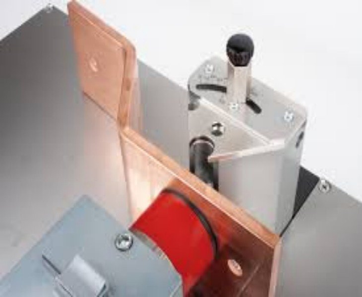
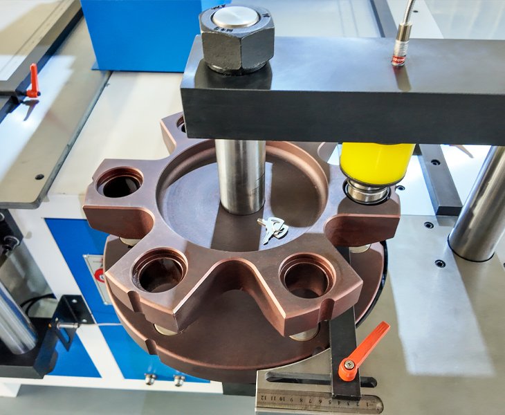
How Should Copper Material Be Confirmed?
Copper grade and temper can affect punching force, burr formation, shearing deformation, bending springback and surface marking.
The material specification should identify the copper grade, temper, width × thickness, raw length, flatness, edge condition, surface-protection requirements and any coating or plating completed before or after fabrication.
Do not approve a machine only from the words “copper busbar.” Confirm representative material for the largest section, smallest hole-to-edge distance, shortest bend leg and most demanding surface requirement.
During sample testing, record the actual material specification and do not substitute a softer or thinner copper bar without written approval.
How Should Punching, Shearing and Bending Be Sequenced?
The process sequence should be determined from the approved finished-part drawing rather than treated as three unrelated machine operations.
Cutting may be completed before punching when the finished end is the approved dimensional datum. A CNC punching-and-shearing line may instead process hole coordinates on long stock before completing the final shear.
Bending is commonly completed after the required punching and shearing operations, but the final sequence should be confirmed from tooling access, deformation risk, workpiece support, hole-to-bend distance, and finished geometry.
After punching, verify that the forming tool does not deform nearby holes or damage the surface. After bending, when punching is completed, confirm that the formed workpiece can enter the punching area and remain properly supported.
| Process Check | What to Confirm |
|---|---|
| Drawing Datum | Finished end, hole centerline or bend reference |
| Punching Sequence | Hole access, edge distance and later deformation |
| Shearing Sequence | Finished length, squareness and end condition |
| Bending Sequence | Tooling interference, springback and support |
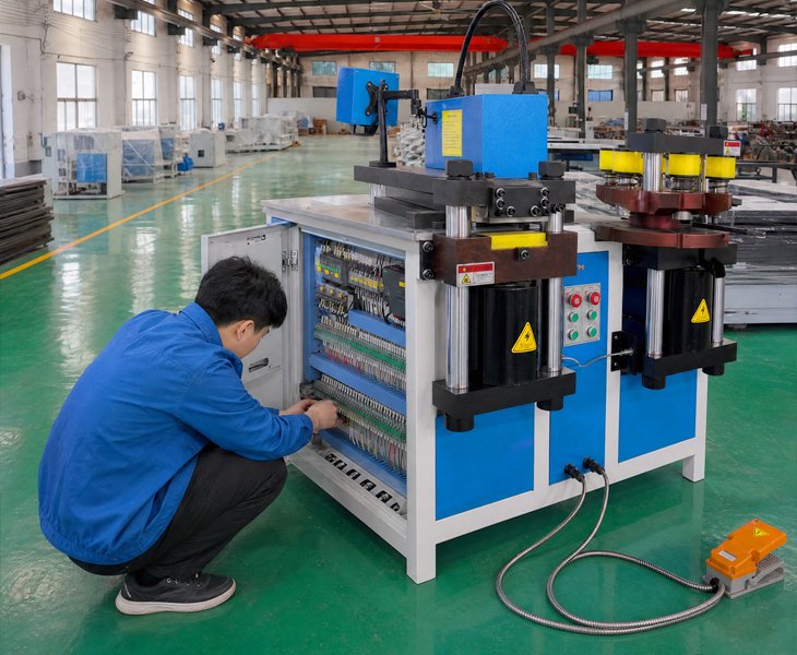
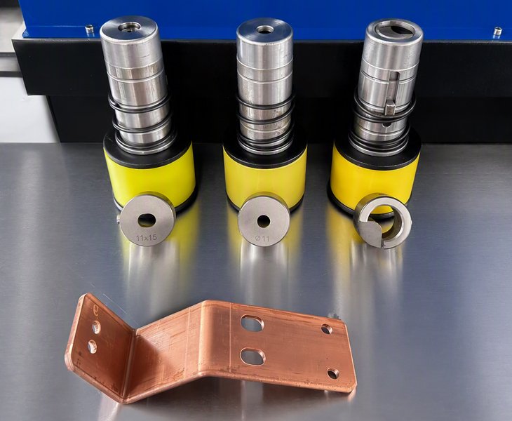
Copper Busbar Fabrication Machine FAT Checklist
| FAT Check | What to Verify | Evidence |
|---|---|---|
| Configuration and Safety | Machine, control, tooling and contracted protection | Configuration sheet and checklist |
| Punching and Shearing | Hole position, geometry, length, burr and end condition | Samples and measurement report |
| Bending and Geometry | Released angle, position, radius, short leg and surface | Inspection report and photos |
| Process and Repeatability | Sequence, beginning/middle/end parts and complete cycle | FAT report and video |
| Documents and Parts | Manuals, drawings, tooling and contracted spare parts | Document index and packing list |
Agree the copper material, drawings, process sequence, sample quantity, measuring instruments and acceptance limits before FAT.
How to Compare China’s Top 10 Busbar Machine Manufacturers for Copper Fabrication
There is no universally recognized official ranking of China’s top 10 busbar machine manufacturers. Published lists should be used only to prepare an initial supplier shortlist.
For a copper busbar fabrication project, compare the exact production route and machine configuration proposed for your finished-part drawings rather than relying only on company size, nominal force or promotional rankings.
| Comparison Factor | What to Confirm | Evidence to Request |
|---|---|---|
| Production Route | Integrated machine or dedicated equipment | Layout and process proposal |
| Operation Capacity | Punching, shearing and bending separately | Signed capacity table and samples |
| Tooling and Handling | Dies, bend tools, positioning and support | Tooling list and demonstration |
| FAT and Service | Finished parts, documents, warranty and parts | Signed FAT and service scope |
For a broader sourcing shortlist, review our guide to 10 Busbar Machine Manufacturers in China. The article is published by FengHua and should not be treated as an official ranking or independent certification.
A copper busbar fabrication machine performs one or more operations such as punching, shearing and bending to produce finished conductive parts from approved drawings.
No. A 3-in-1 machine is suitable when punching, shearing and bending are regularly required in one working area. Repetitive or higher-output parts may be better produced with dedicated punching, shearing or bending equipment.
The correct sequence depends on the approved drawing datum, raw-bar handling, feeding system and finished-length requirement. Both sequences may be valid when supported by the selected equipment and inspection plan.
It depends on the hole-to-bend distance, tooling access, deformation risk and finished geometry. Review the complete drawing before defining the sequence.
No. Punching, shearing and bending capacity should be confirmed separately according to the copper temper, material size, hole geometry, blade, bending radius and tooling.
No. CNC or PLC control may manage selected coordinates or machine functions. Loading, movement, rotation, tooling changes, final alignment and inspection may remain manual.
Measure hole and slot positions, finished length, cut squareness, released bend angle, bend position, overall geometry, burr, deformation and surface condition from the approved drawing datums.
Compare complete cycle time using the same copper material and finished-part drawing. Include setup, tooling, positioning, all operations, inspection, operator count and rejected parts.
Provide the copper grade and temper, material dimensions, drawings, operations, tolerances, batch mix, output, voltage, workshop layout and FAT requirements.
Use representative copper material and finished-part drawings to verify every required operation, tooling, positioning, repeatability, complete cycle, safety, documents and spare parts.