

Quick Answer
A busbar bending and punching machine combines dedicated hole-processing and bending functions for copper or aluminum busbars.
The operator may need to move, rotate and reposition the workpiece between the punching and bending operations. Digital or CNC control may provide positioning references, but it does not automatically mean that material feeding, tooling changes or the complete process is automatic.
Cutting is included only when a separate shearing station is specified in the approved machine configuration. Select the equipment according to the operation-specific capacity, hole geometry, bend structure, tooling, positioning method, workpiece handling and FAT criteria.
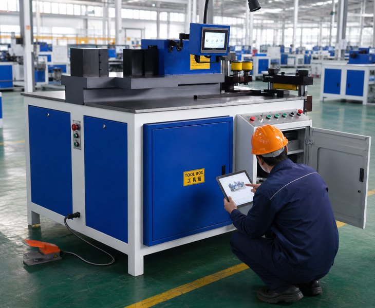
What Is a Busbar Bending and Punching Machine?
A busbar bending and punching machine combines dedicated punching and bending functions within one machine or coordinated working area.
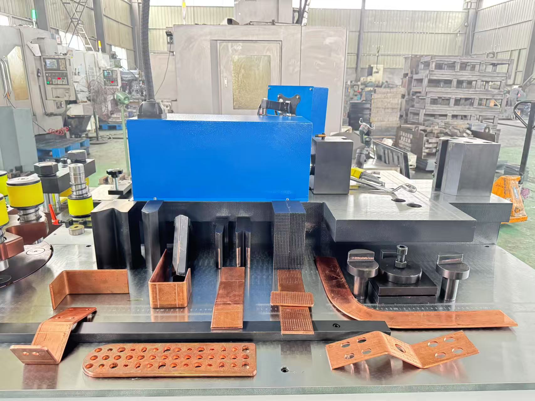
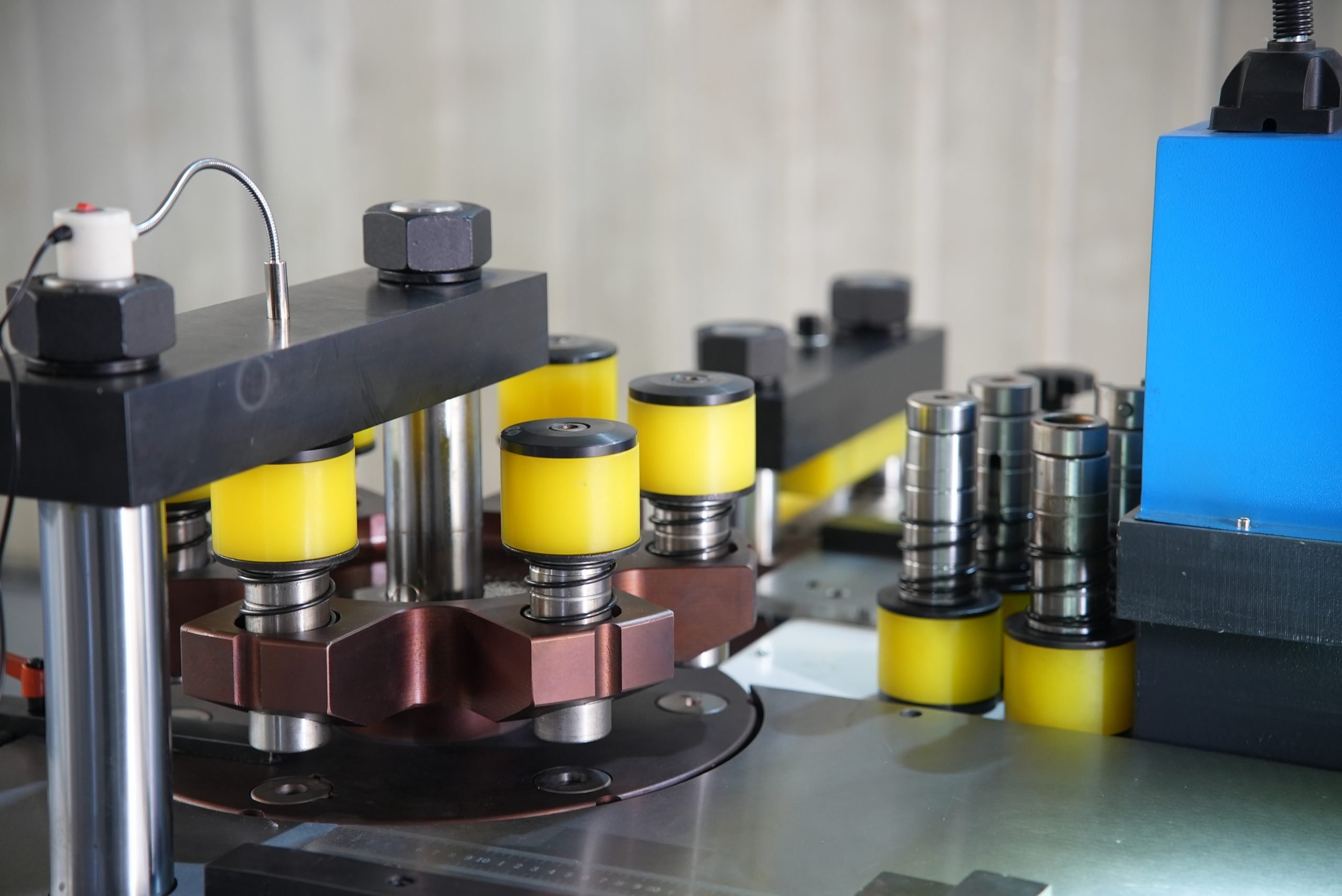
The punching unit produces connection holes, mounting holes or slots using matched punches and dies. The bending unit forms the busbar according to the required angle, radius, direction and finished geometry.
The busbar may require separate positioning, rotation and support for each operation. The machine should not be described as completing every process in one positioning unless the exact workpiece, tooling and control sequence have been demonstrated.
Punching force, bending force, positioning method, tooling and material handling should be confirmed separately against representative customer drawings.
Busbar Bending and Punching Machine Configurations
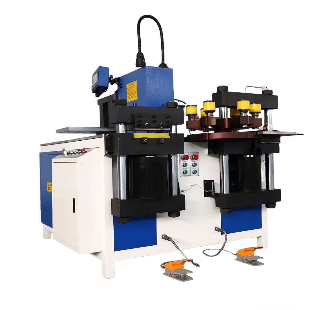
A flexible configuration for mixed small- and medium-batch projects using manual or stop-assisted positioning. Confirm the punching force, bending force, tooling range and workpiece-support requirements.
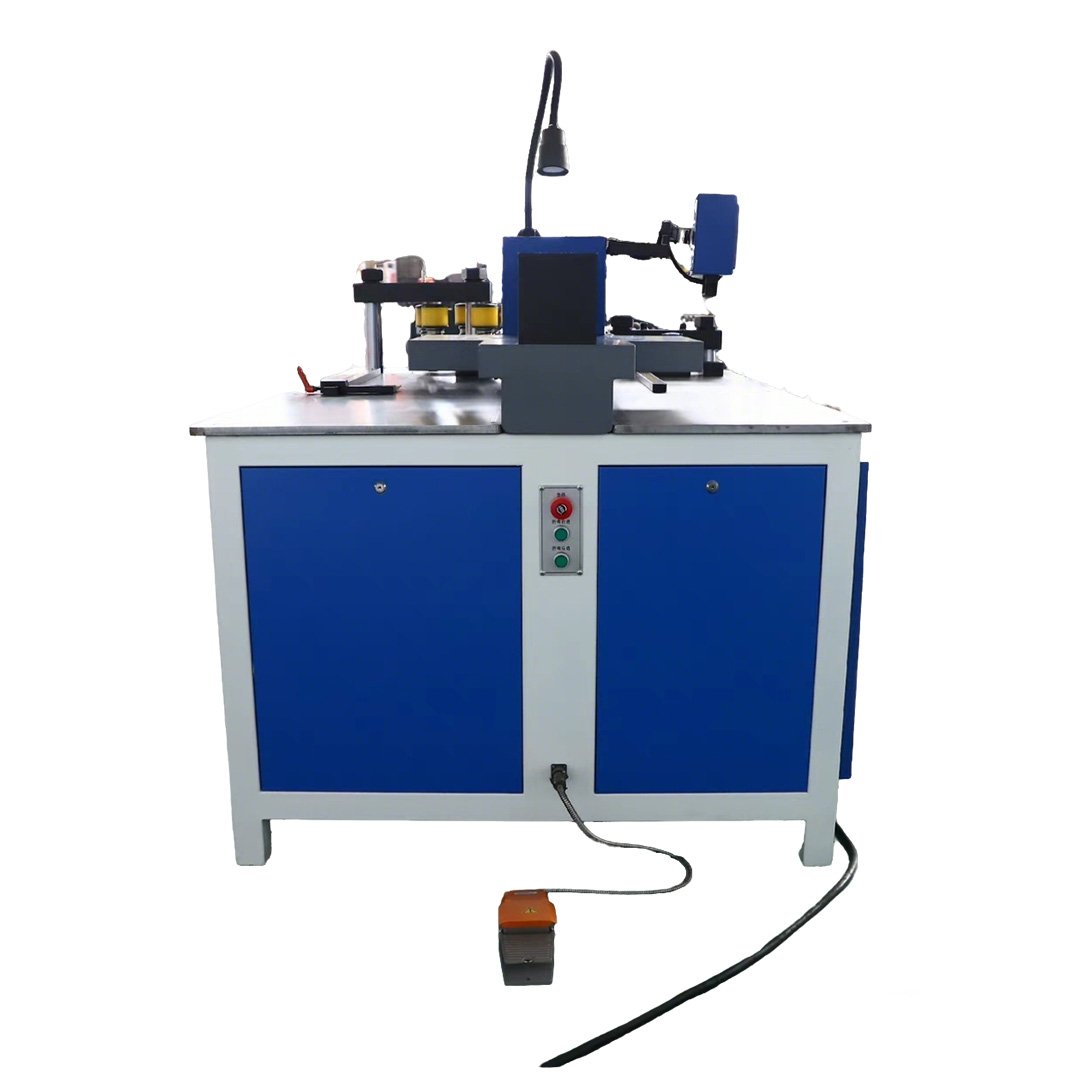
Suitable for recurring hole positions or bend locations requiring programmable positioning references. Confirm the controlled axes, program functions, feeding method and manual operations.
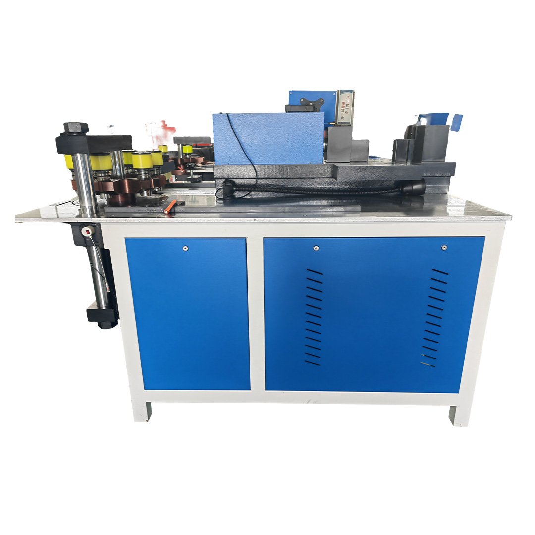
Reviewed for projects processing different conductive materials and busbar dimensions. Confirm the grade or alloy, temper, width × thickness, hole geometry and bending tooling separately.
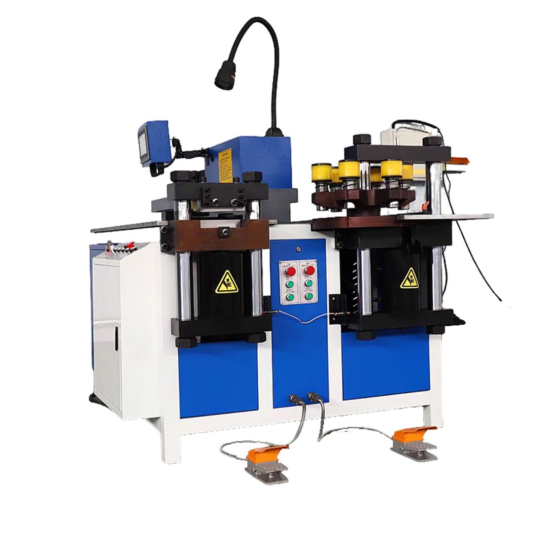
Configured for non-standard holes, slots, bend profiles, short legs, special radii, positioning requirements or workshop layouts.
Busbar Bending and Punching Machine vs. 3-in-1 Busbar Machine
| Comparison | Bending and Punching Machine | 3-in-1 Busbar Machine |
|---|---|---|
| Main Functions | Punching and bending | Punching, shearing and bending |
| Best Fit | Parts cut separately or supplied at final length | Projects requiring all three operations |
| Main Confirmation | Hole and bend relationship, tooling and positioning | Capacity and workflow of all three stations |
| Selection Risk | Assuming cutting is included | Assuming all processes are fully automatic |
Choose a two-process configuration when cutting is completed separately or the raw parts are supplied at the required length. Choose a 3-in-1 machine when punching, shearing and bending are all regularly required within the same production area.
Functions to Confirm Before Selecting a Busbar Bending and Punching Machine

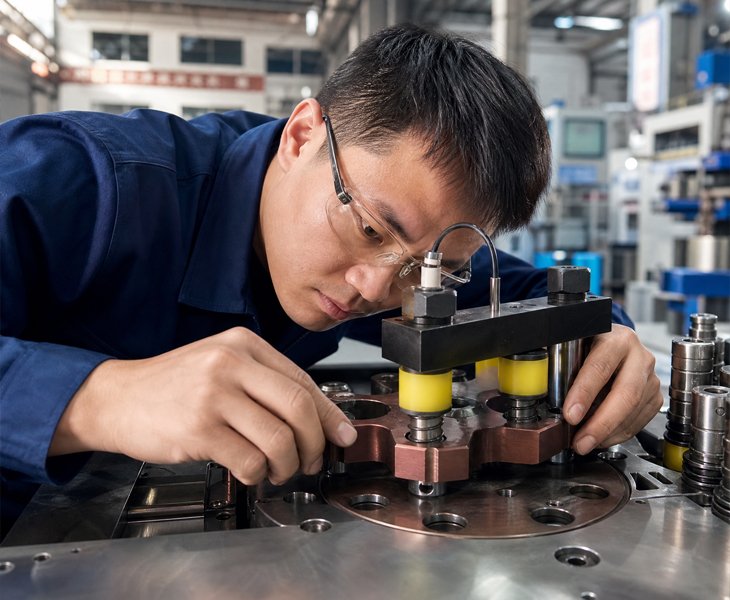
Confirm the applicable material, punching force, supported hole and slot dimensions, punch-and-die clearance, minimum hole-to-edge distance, hole-center pitch, throat reach and included die list.

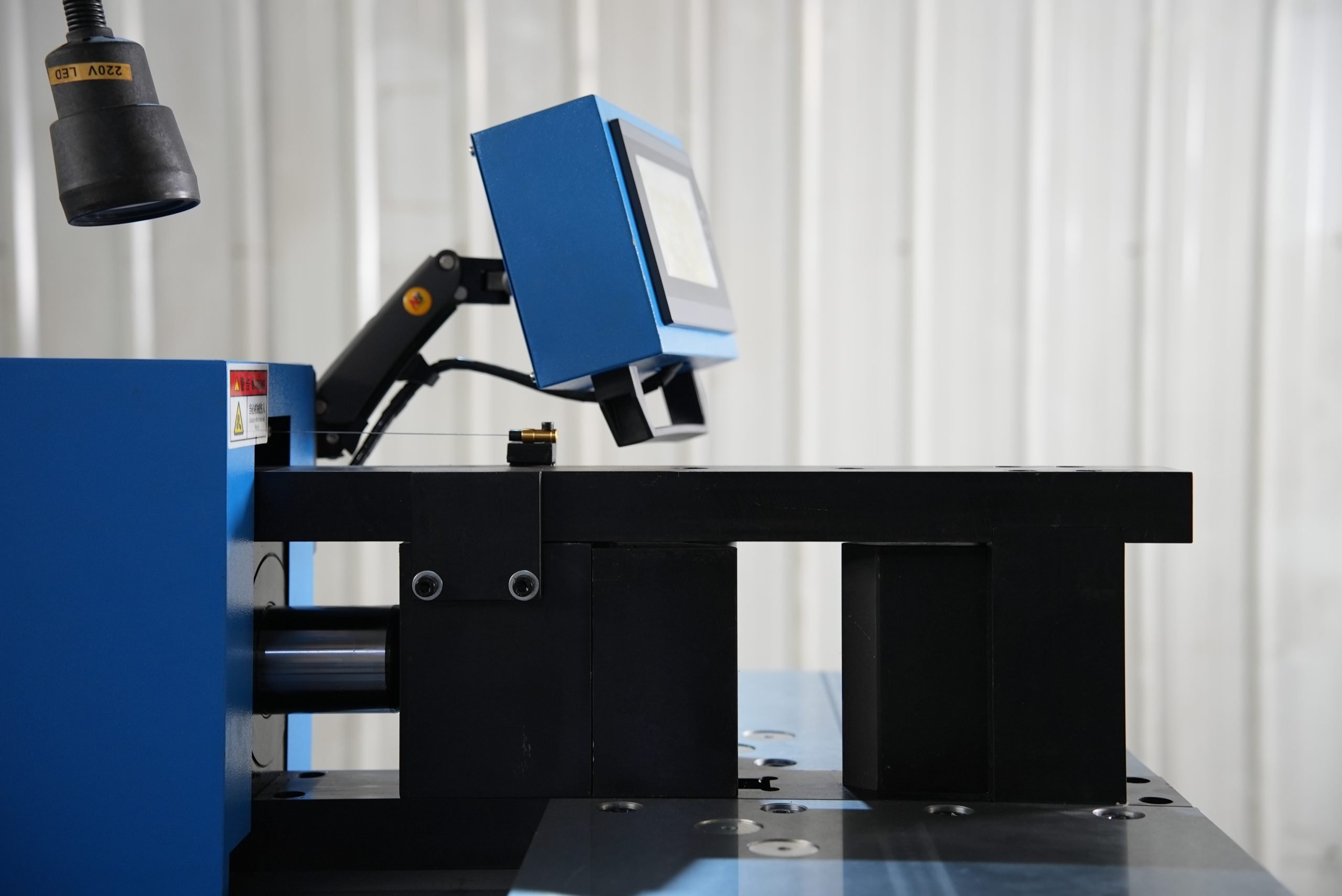
Confirm flat or vertical bending capability, material width × thickness, inside radius, minimum short-leg length, bend direction, tooling clearance, springback adjustment and surface requirements.

Confirm whether hole and bend locations are set manually, through mechanical stops, with digital measurement or by servo-controlled positioning. Specify the drawing datum and controlled axes.

Confirm material loading, movement between operations, rotation, alignment, long-busbar support, operator requirements and workshop clearance.
How Should Punching Accuracy Be Verified?
Positioning accuracy, finished-hole accuracy and repeatability should be defined as separate acceptance items.
Positioning accuracy describes how closely the positioning system reaches a commanded coordinate. Finished-hole accuracy describes the measured hole location relative to the approved drawing datum. Repeatability describes the variation across consecutive finished parts.
Hole quality should also be evaluated by the diameter or slot dimensions, burr, edge deformation, surface condition and tool marks.
| Inspection Item | What to Confirm |
|---|---|
| Hole Position | X and Y dimensions from the approved datum |
| Hole Geometry | Diameter, slot length and slot width |
| Edge Quality | Burr, deformation and surface marks |
| Repeatability | Variation across consecutive finished parts |
Do not publish a universal ±0.1 mm claim until the exact machine, positioning system, material, workpiece length, drawing datum, sample quantity and FAT method are confirmed.
How Should Busbar Bending Accuracy Be Verified?
Bending accuracy should be measured on the released workpiece after springback rather than only from the machine stroke or tooling position.
Confirm the material grade or alloy, temper, width × thickness, bend direction, inside radius, short-leg length, tooling, drawing datum and finished-angle tolerance.
For repeated parts, inspect samples produced at the beginning, middle and end of the agreed test run. Record the programmed value, released angle, bend position, surface condition and any correction applied.
| Inspection Item | What to Confirm |
|---|---|
| Released Angle | Measured after the workpiece leaves the die |
| Bend Position | Distance from the approved drawing datum |
| Radius and Short Leg | Tooling compatibility and finished geometry |
| Surface Quality | Cracking, indentation, twisting and marks |
Do not publish a general angle tolerance or hourly output until the representative material, drawing, complete cycle and acceptance method have been tested.
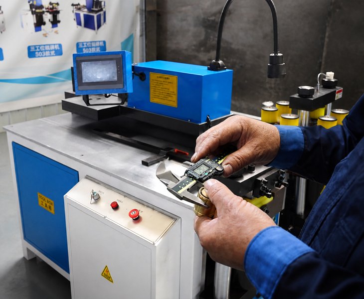
How Does the Punching and Bending Workflow Operate?
Punching and bending are completed through separate operations using the approved tooling for each process.
The operator may need to align, reposition, rotate and support the busbar according to the hole layout, bend direction and finished geometry. Digital or CNC functions may provide coordinate or position references, while material handling and final alignment can remain manual.
The technical quotation should define the processing sequence, positioning method, tooling changes, operator involvement and whether any operation requires separate equipment.
How Should Punching and Bending Be Coordinated?
A finished busbar may require holes to remain correctly positioned after one or more bends. The process sequence should therefore be reviewed from the complete finished-part drawing.
Confirm the drawing datum, hole-to-bend distance, bend allowance, inside radius, springback, tooling interference, orientation and dimensional inspection method.
When the bend is completed after punching, verify that the tooling and workpiece support do not deform the hole or damage the surrounding surface. When punching is completed after bending, confirm that the formed part can still enter the punching area and remain correctly supported.
| Drawing Check | What to Confirm |
|---|---|
| Hole-to-Bend Distance | Measurement datum and finished tolerance |
| Process Sequence | Punch first or bend first |
| Tooling Clearance | Interference with holes and formed sections |
| Finished Inspection | Hole position, bend position and overall geometry |
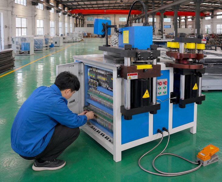
Busbar Bending and Punching Machine FAT Checklist
| FAT Check | What to Verify | Evidence |
|---|---|---|
| Configuration and Safety | Machine, control, tooling and contracted protection | Configuration sheet and checklist |
| Punching | Hole position, geometry, edge distance and burr | Sample and measurement report |
| Bending | Released angle, bend position, radius and short leg | Sample and inspection report |
| Combined Part | Hole-to-bend relationship, surface and overall geometry | Finished-part drawing and photos |
| Documents and Parts | Manuals, drawings, tooling and contracted spare parts | Document index and packing list |
Agree the material, drawing, processing sequence, sample quantity, measuring instruments and acceptance limits before FAT.
How to Compare China’s Top 10 Busbar Machine Manufacturers for Punching and Bending Projects
There is no universally recognized official ranking of China’s top 10 busbar machine manufacturers. Published lists should be used only to create an initial supplier shortlist.
For a punching and bending project, compare the exact machine proposed for your material and finished-part drawings rather than relying only on company size, nominal force or promotional rankings.
| Comparison Factor | What to Confirm | Evidence to Request |
|---|---|---|
| Machine Scope | Punching and bending, or full 3-in-1 processing | Model, layout and configuration |
| Operation Capacity | Punching and bending limits separately | Signed capacity table and samples |
| Tooling and Positioning | Dies, bend tools, datum and controlled functions | Tooling list and demonstration |
| FAT and Service | Finished parts, criteria, documents and parts | Signed FAT and service scope |
For a broader sourcing shortlist, review our guide to 10 Busbar Machine Manufacturers in China. The guide is published by FengHua and should not be treated as an official ranking or independent certification.
High-Efficiency Busbar Punching Bending Cutting Machine
Achieve Precise Copper & Aluminum Busbar Processing for Switchgear and Power Distribution Systems
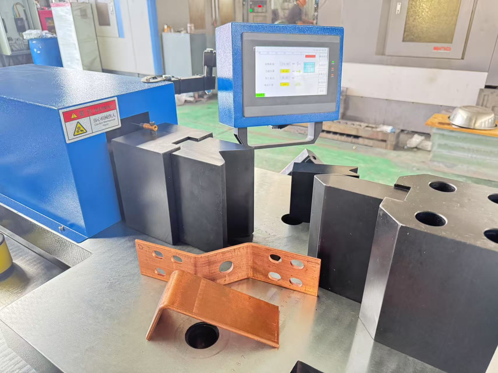
Through the CNC visual operation interface, you only need to input the new specification parameters, and Fenghua’s busbar stamping, bending, and cutting machine can automatically adjust the cutting length, drilling position, and bending angle of the busbar.
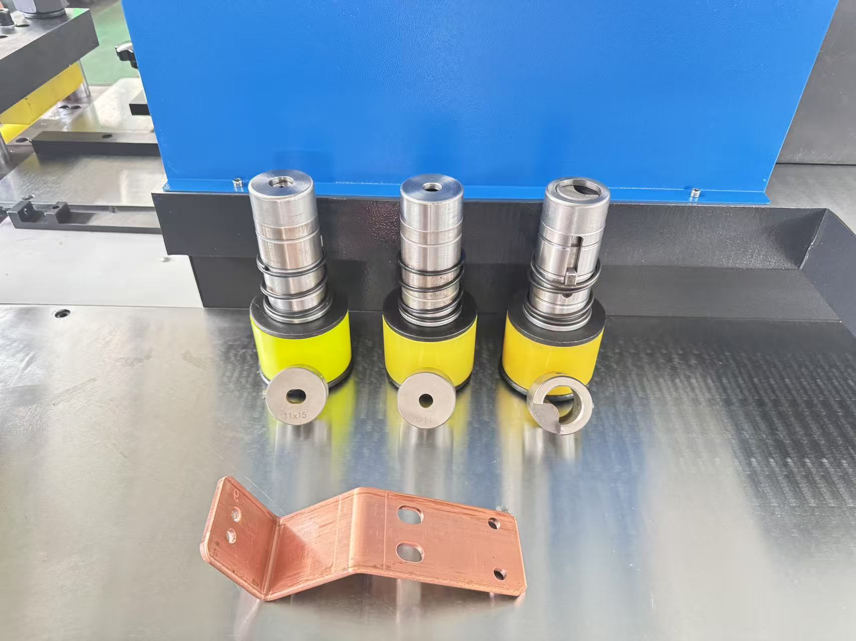
Fenghua’s busbar stamping, bending, and cutting machine features a fully enclosed protective cover and a real-time monitoring system. When the hydraulic and servo systems of your production line equipment malfunction, it will automatically stop and alarm, ensuring a high degree of safety in your industrial busbar production line.
A busbar bending and punching machine combines dedicated hole-processing and bending functions for copper or aluminum busbars.
Not necessarily. Cutting is included only when a separate shearing station is listed in the approved configuration. Otherwise, the material must be cut using separate equipment or supplied at the required length.
It may process both materials subject to technical confirmation. Capacity depends on the material grade or alloy, temper, width, thickness, hole geometry, bend structure and tooling.
Not in every configuration. Positioning, workpiece movement, rotation, tooling changes, alignment and inspection may remain manual even when selected coordinates or parameters are digitally controlled.
No. Positioning accuracy describes movement of the positioning system. Finished-hole accuracy is measured from the approved drawing datum and can also be affected by tooling clearance, workpiece movement and material support.
Measure the released workpiece after springback. Confirm the angle, bend position, radius, short leg, surface condition and finished geometry against the approved drawing.
The correct sequence depends on the finished-part geometry, hole-to-bend distance, tooling clearance and workpiece support. Review the complete drawing before defining the process sequence.
Provide the material, width × thickness, raw length, hole drawing, bend geometry, tolerances, batch quantity, output, voltage and preferred positioning method.
Use representative material and finished-part drawings to verify punching, bending, positioning, combined geometry, repeatability, tooling, safety, documents and spare parts against the agreed FAT criteria.

