Quick Answer
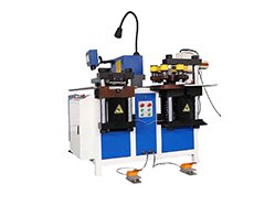
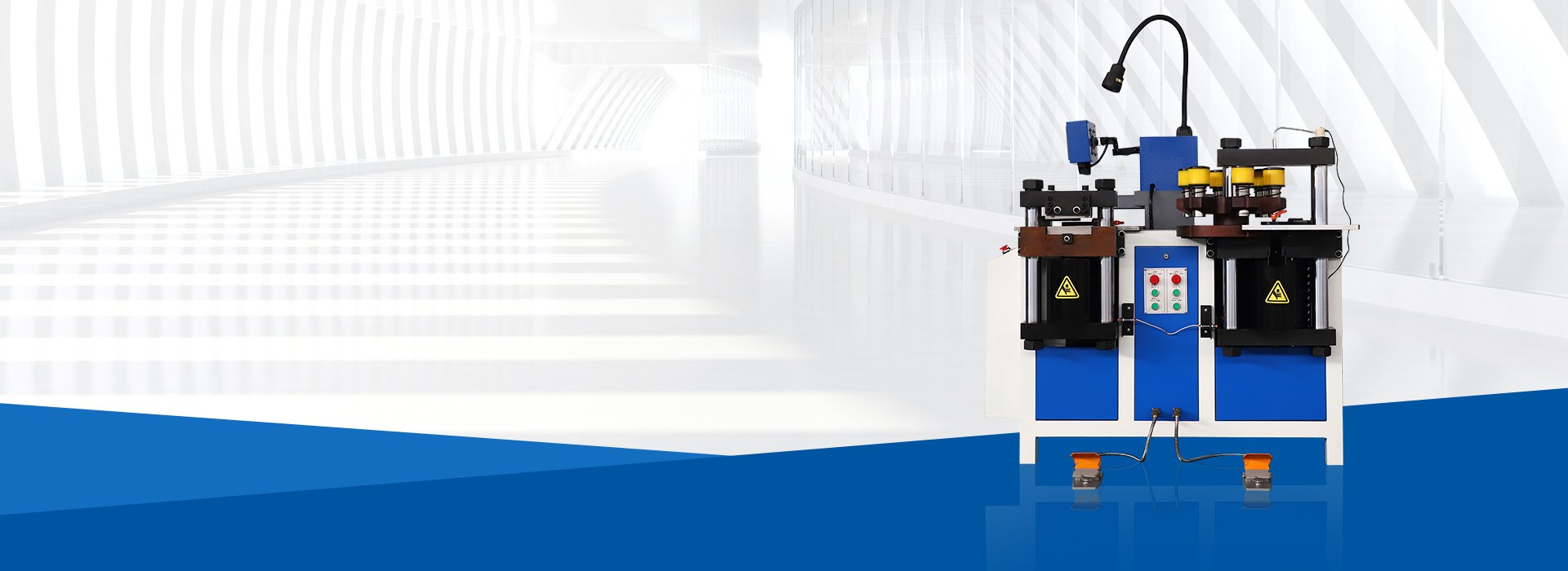
A busbar bending machine forms copper or aluminum busbars into drawing-specific angles and profiles using matched bending tooling.
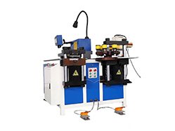
FengHua’s available range includes a CNC Servo model for customized flat and vertical bends and a Double-Head model for repetitive double-end busduct conductors.
The correct configuration depends on the material grade or alloy, temper, width × thickness, bend direction, inside radius, minimum short-leg length, positioning method, tooling and required production output.
Busbar Bending Machine Manufacturer for Drawing-Based Production
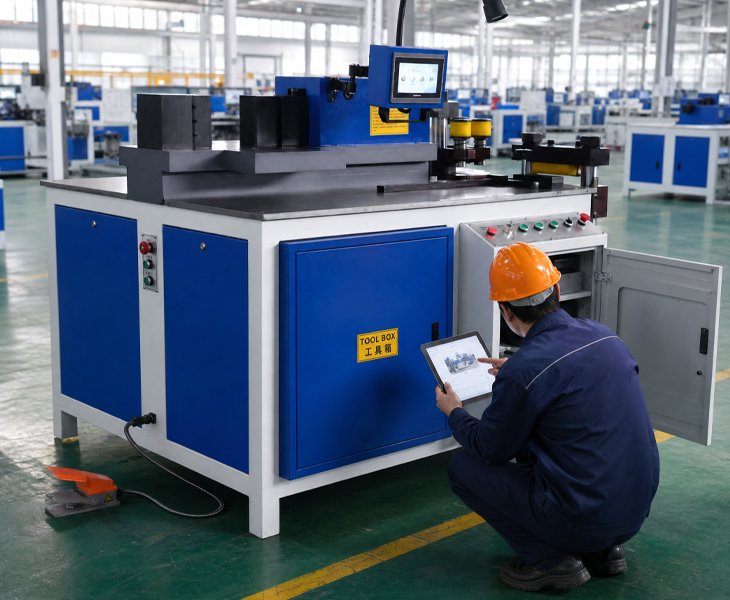
FengHua configures busbar bending equipment according to the finished workpiece rather than only the nominal machine force. Before quotation, the engineering review should confirm the material grade or alloy, temper, width × thickness, raw-bar length, bend direction, inside radius, minimum short-leg length, number of bends, required tolerance and batch output.
The technical quotation should identify the exact machine model, supported bending operations, included tooling, positioning method, material-handling requirements, electrical configuration, FAT samples, documentation, warranty scope and spare-parts list.
Choose the Right Busbar Bending Machine
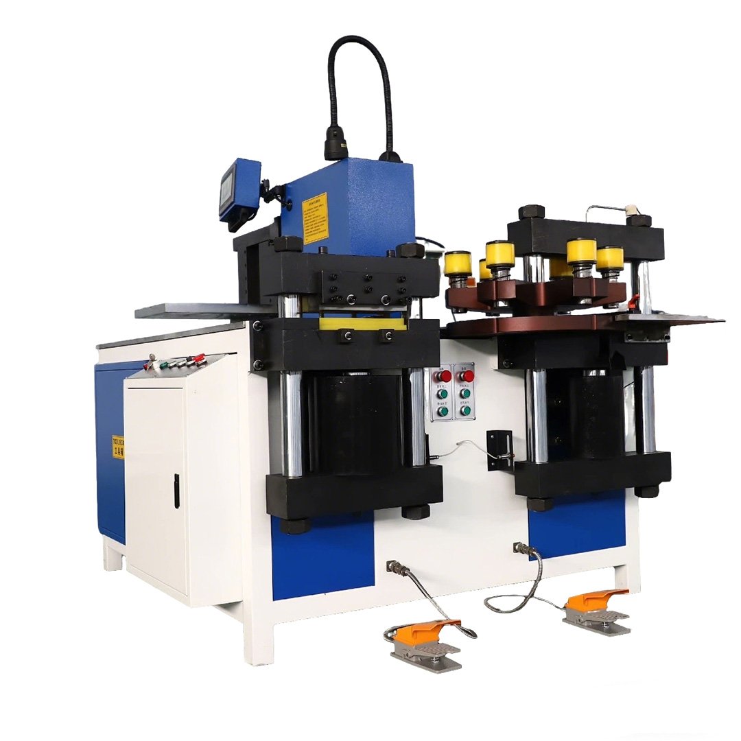
Dedicated hydraulic forming for customized copper and aluminum busbar production. Confirm the required force, stroke, tooling radius, bend direction and maximum busbar size against your drawing.
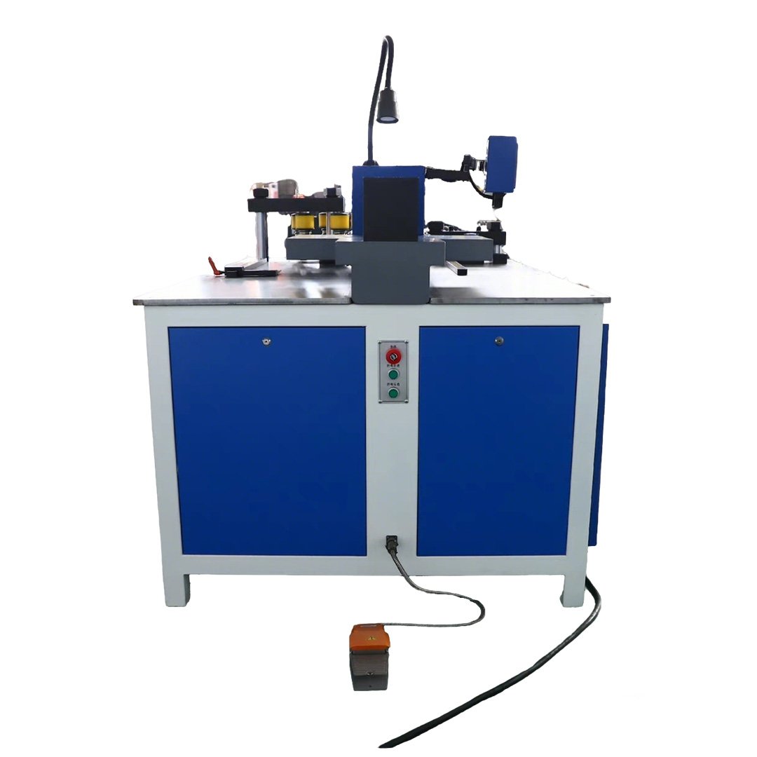
Suitable for recurring bend positions, frequent product changes and program-based production. Confirm the controlled axes, positioning range, program storage and finished-part acceptance tolerance.
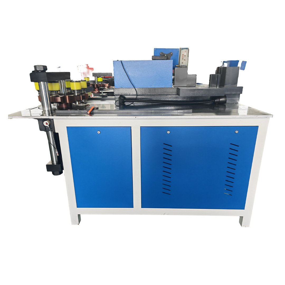
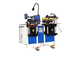
Designed for busduct or busway conductors requiring forming operations at both ends. Confirm head spacing, workpiece length, bend sequence, tooling, material support and whether the listed force is per head or total.
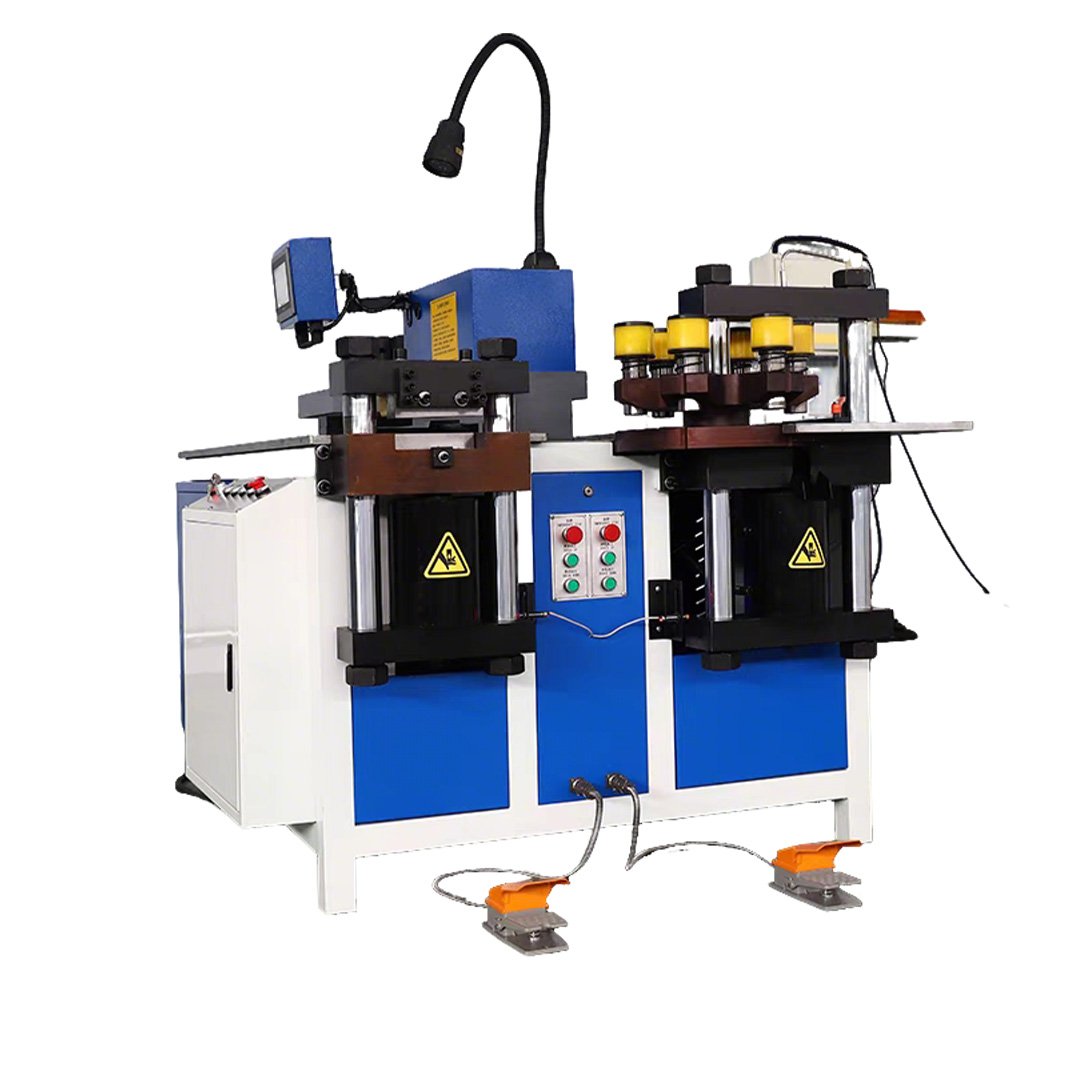
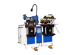
MX-303, MX-503 and MX-803 models combine punching, cutting and bending. Available model references cover maximum overall busbar sizes from 160 × 16 mm to 300 × 20 mm.
Which Busbar Bending Machine Should You Choose?
Choose the machine according to the finished-part drawing, material condition, required bending operations, positioning method and accepted output—not only according to nominal force or the word “CNC.”
| Production Requirement | Starting Configuration | Critical Buyer Check |
|---|---|---|
| Flexible mixed-specification production | Hydraulic busbar bending machine | Force, stroke, tooling, setup time and operator positioning |
| Recurring bending positions and frequent model changes | CNC or servo-assisted bending solution | Controlled axes, program recall and positioning versus finished-part tolerance |
| Repetitive double-end conductors | Double-head busbar bending machine | Head spacing, workpiece support, force definition and total cycle time |
| Punching, cutting and bending in one working area | MX-series 3-in-1 machining center | Capacity of every station, punch range, tooling and station independence |
What Should You Compare in a Busbar Bending Machine?

Confirm flat bending, vertical bending, offset bending and special-profile capacity separately. A catalogue maximum does not automatically apply to every bending direction and die.

Separate controller resolution, positioning accuracy, repeatability and released finished-part tolerance. These values describe different parts of the process.

Confirm the included dies, inside radius, short-leg limit, die clearance, machine-frame clearance and bend sequence using the complete drawing.

Evaluate loading, positioning, tooling adjustment, bending, unloading and inspection. Hydraulic stroke speed alone does not represent accepted parts per shift.
Customized Busbar Bending Machine Solutions
A custom configuration should begin with the finished-part drawing. FengHua reviews the material grade or alloy, temper, busbar width and thickness, raw length, bend direction, inside radius, minimum short-leg length, number and sequence of bends, required tolerance, batch quantity and workshop power supply.
The approved quotation should state the exact machine model, confirmed processing range, included tooling, optional tooling, controlled axes, loading method, electrical components, safety configuration, FAT samples, documentation and service scope.
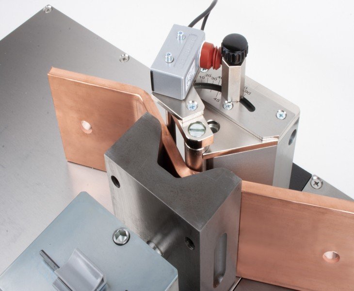
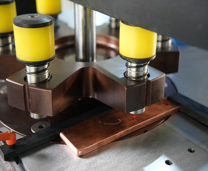
Send Standard, Maximum and Complex Part Drawings
Fenghua busbar bending machines are equipped with advanced CNC systems, bending angles, and busbar travel. Every movement in the bending process is set through repeated manual adjustments. stress distribution on the busbar during the bending of high-volume, continuous busbar processing production lines, improving your production efficiency.
How to Evaluate Busbar Bending Cycle Time
Do not compare machines using hydraulic stroke speed alone. Complete cycle time should include material loading, positioning, tooling adjustment, bending, part removal and inspection. For a fair supplier comparison, test the same workpiece, material, drawing and acceptance tolerance.
Record the number of operators, setup time, complete cycle time, conforming parts produced, rejected parts and any repositioning steps.
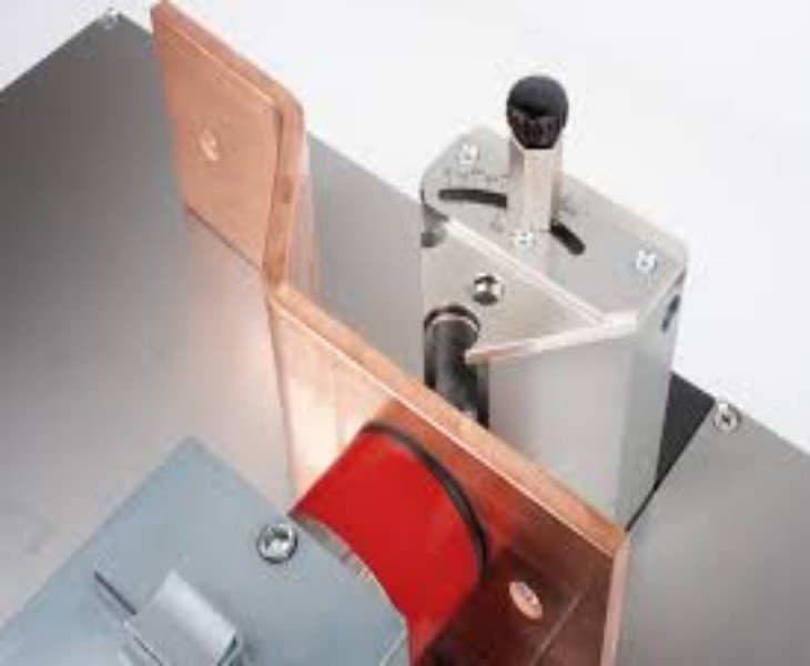
Busbar Bending Machine FAT Acceptance Checklist
| FAT Check | What to Confirm |
|---|---|
| Machine | Model and approved configuration |
| Material | Grade, size and test drawing |
| Tooling | Dies and bending radius |
| Results | Angle, dimensions and repeatability |
| Acceptance | Safety, documents and sign-off |
Do not approve the machine based on one successful sample. The FAT should include representative materials, multiple parts and the most difficult workpiece drawing.
How to Verify Busbar Bending Accuracy
Busbar bending accuracy should be verified on the released finished part rather than only from the controller display. Positioning accuracy describes where the material or backgauge is moved. Repeatability describes variation under the same setup. Finished-angle tolerance describes the difference between the required and measured angle after the workpiece is released from the tooling.
Material grade, temper, width, thickness, inside radius, short-leg length, tooling and springback can all affect the final result. The FAT should therefore use representative material and drawing-based samples.
| Test Item | What to Record |
|---|---|
| Material | Standard, grade or alloy and temper |
| Busbar Size | Width × thickness |
| Bending Direction | Flat, vertical, offset or double-end |
| Tooling | Die type and inside radius |
| Target Angle | Drawing requirement |
| Released Angle | Measured after removal from tooling |
| Bend-Line Position | Required and measured position |
| Short-Leg Length | Required and measured value |
| Surface Condition | Scratches, impressions, cracks or deformation |
| Repeatability | Results from an agreed sample quantity |
| Inspection Tool | Angle gauge, caliper, fixture or CMM method |
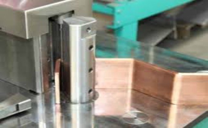
The word “CNC” should not be used as a substitute for a complete machine specification. Confirm which axes are controlled, whether material feeding remains manual, how bend positions are entered, whether programs can be stored and recalled, and how first-part correction is completed after changes in material or tooling.
Where a servo positioning unit is included, record the positioning range, accuracy, repeatability, load, speed, interface and safety limits in the quotation.
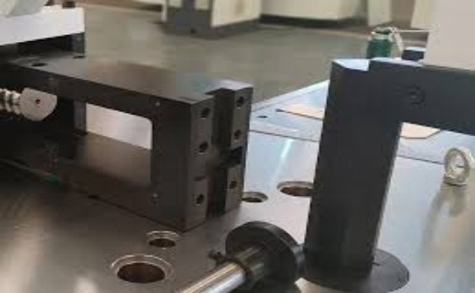
A China Top 10 busbar machine manufacturer list should be used as a supplier-comparison starting point rather than proof of machine quality. Final selection should be based on the exact machine model, operation-specific capacity, controlled axes, tooling, representative samples, FAT results, documentation and after-sales scope.
A supplier’s general busbar-machine experience does not automatically prove that every hydraulic, CNC or double-head bending configuration meets your workpiece requirements. Request evidence for the exact machine proposed in the quotation.
Hydraulic describes how the bending force is generated. CNC describes programmable control. A CNC busbar bending machine may still use a hydraulic forming system. Compare the controlled axes, positioning method, material handling, tooling and finished-part test rather than only the machine name.
No. Servo positioning accuracy describes the movement of the positioning system. Finished bending accuracy must be measured on the released workpiece and can also be affected by the material, tooling, radius, short-leg length and springback.
It may process both materials when the machine and tooling are correctly configured. Confirm the material grade or alloy, temper, width, thickness, bend direction, radius and surface requirements separately.
Confirm flat bending, vertical bending and special-profile bending separately. Use the actual material and drawing because nominal width, thickness or force values do not describe every bend geometry.
Choose a dedicated bending machine when tooling flexibility, bend geometry or parallel production is the priority. Choose a 3-in-1 machining center when punching, cutting and bending are required in one working area and the capacity of every station matches your parts.
Provide the material standard, grade or alloy, temper, width × thickness, raw length, bend direction, target angle, inside radius, minimum short-leg length, number of bends, finished-part tolerance, batch quantity, local voltage and dimensioned drawings.