
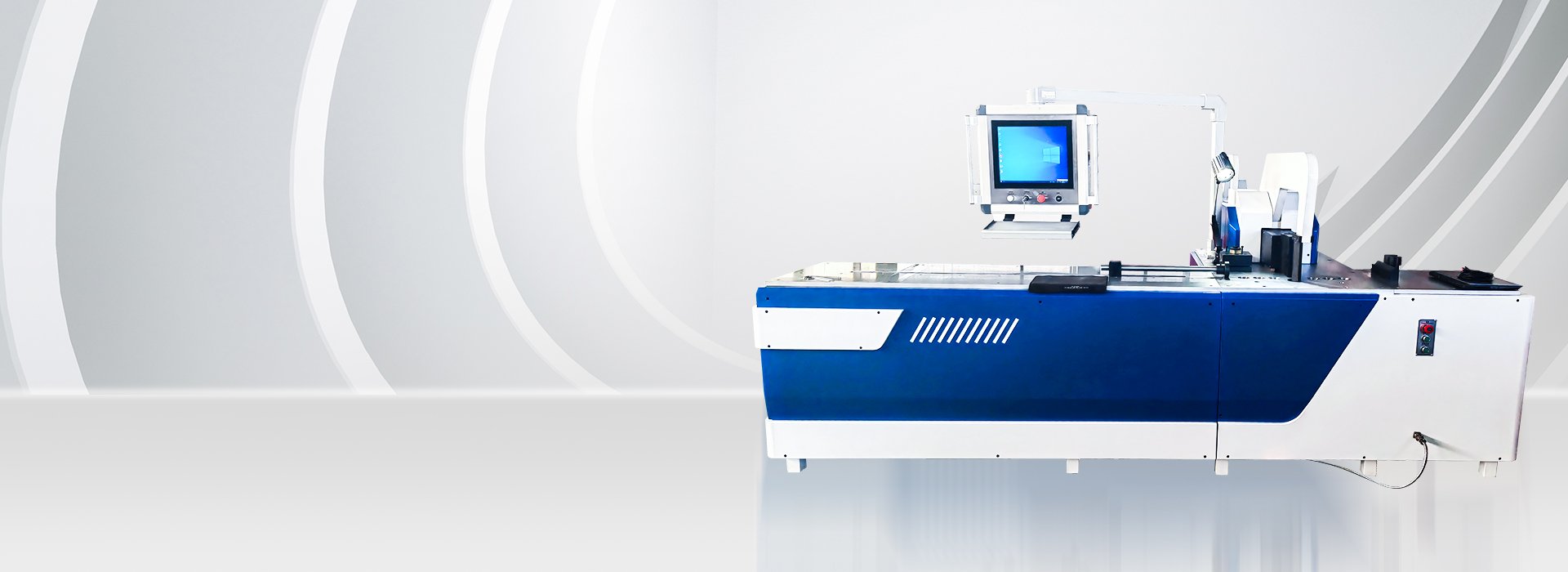
Quick Answer: What Does CNC Control on a Busbar Bending Machine?
CNC refers to programmed control of one or more machine variables. Depending on the approved configuration, this may include the bending stroke, target angle, servo backgauge position or production recipe.
CNC does not automatically mean that material loading, alignment, feeding, tool changing, unloading and inspection are fully automatic. Confirm every controlled axis and remaining manual step in the technical quotation.
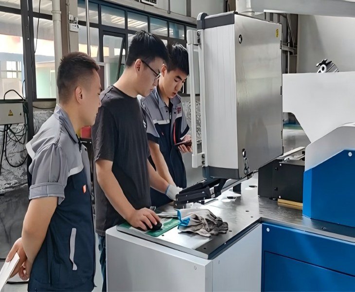
CNC Busbar Bending Machine Manufacturer for Drawing-Based Production
FengHua configures CNC busbar bending equipment according to the finished workpiece rather than only the nominal bending force or the word “CNC.”
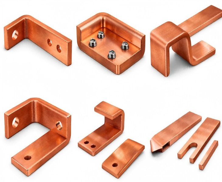
Before quotation, the engineering review should confirm the material grade or alloy, temper, width × thickness, raw-bar length, flat or vertical bending direction, inside radius, minimum short-leg length, number and sequence of bends, finished-part tolerance and required output.
The technical quotation should identify the exact machine model, nominal bending force, controlled axes, positioning range, included tooling, optional tooling, material-loading method, safety configuration, FAT samples, documentation, warranty and recommended spare parts.
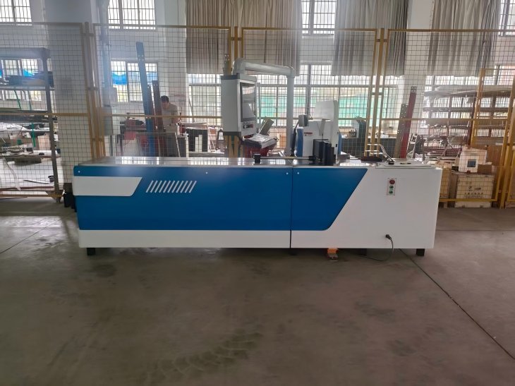
Fenghua CNC Busbar Bending Machine
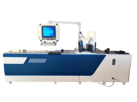
For recurring bend positions and mixed production batches. Confirm the controlled positioning axis, effective range, load capacity, program storage and whether material loading remains manual.
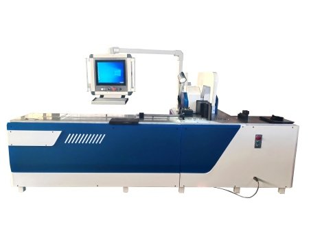
For drawing-based flat bends, offsets, Z profiles and other approved geometries. Confirm the material capacity, inside radius, short-leg limit, tooling and springback correction method.
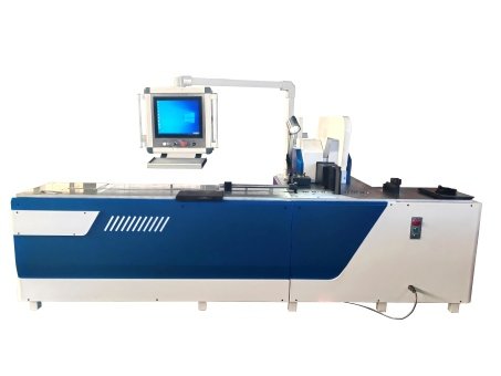
For edgewise or vertical busbar bending with dedicated tooling. Confirm vertical-bending capacity separately from flat-bending capacity, including die clearance, twist and material support.
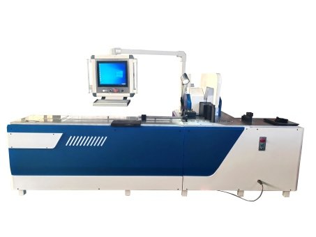
For special profiles, long workpieces, external roller supports, customized dies or factory-specific control requirements. Final capacity and functions are defined through drawing review and FAT.
Which CNC Busbar Bending Configuration Should You Choose?
| Production Requirement | Starting Configuration | Main Check |
|---|---|---|
| Recurring bend positions | Servo-positioned CNC machine | Controlled axis and program recall |
| Standard flat profiles | CNC flat-bending configuration | Capacity, radius and short leg |
| Edgewise bending | CNC vertical-bending configuration | Separate vertical capacity and tooling |
| Special profiles or long parts | Customized CNC system | Interference, support and FAT |
The correct configuration is determined by the finished-part drawing, material condition, tooling and controlled axes—not only by nominal force.
What Should You Confirm in a CNC Busbar Bending Machine?

Confirm whether the CNC controls bending stroke, target angle, servo backgauge position, feeding position or only stored process settings.

Confirm the included dies, inside radius, short-leg limit, tooling clearance and method used to correct material springback.

Separate controller resolution, positioning accuracy, repeatability and released finished-angle tolerance. These are not interchangeable values.

Confirm which loading, alignment, feeding, bending, unloading and inspection steps remain manual in the approved configuration.
Customized Busbar Bending Machines
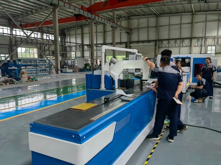
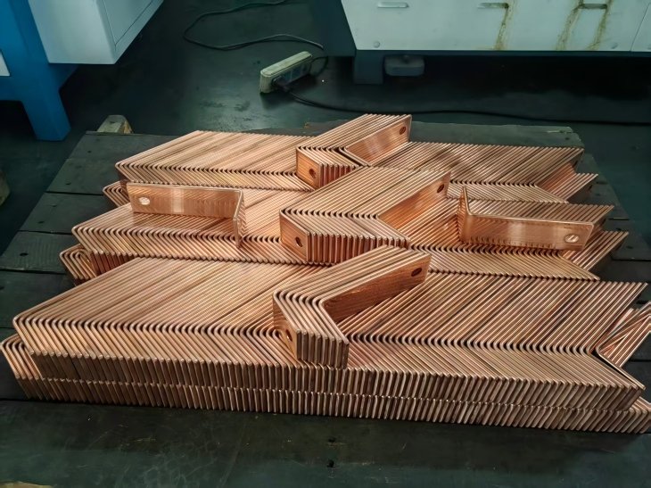
FengHua CNC’s busbar bending machine technical team, customers’ actual busbar requirements, production environment, busbar material, thickness, bending angles, and degree of automation. They will then precisely process and control the system and molds of the busbar bending machine to improve the capacity and yield rate of your busbar processing production line.
How Should CNC Busbar Bending Accuracy Be Verified?
The working process of the Fenghua CNC busbar bending machine is controlled by a CNC system. Bending angles, material feed, and processing sequence can all be precisely set. With pre-set process parameters and a highly rigid machine structure, the CNC busbar bending machine can improve the yield rate of your production line and manual operation. adjustments for your large-volume busbar processing projects and shortening delivery times.
How Should CNC Operation and Changeover Be Evaluated?
A visual interface can simplify parameter entry and program recall, but it does not remove the need for tooling setup, material verification and first-part inspection.
Confirm how operators select the drawing revision, load the correct program, install the approved tooling, enter material information, perform the first bend, measure the released part and save any approved correction value.
Optional Servo Positioning System
| Item | Uploaded Reference |
|---|---|
| Positioning Length | 0–3,000 mm, customizable |
| Positioning Accuracy | ±0.05 mm |
| Repeat Positioning | ±0.02 mm |
| Busbar Range | 20–200 mm W × 1–10 mm T |
| Control | PLC, touchscreen and closed-loop servo |
These are example reference values for the uploaded servo positioning unit, not guaranteed finished-bend tolerances. Final range, load, speed, interface and accuracy must be stated for the approved CNC bending-machine configuration.
How to Compare China’s Top CNC Busbar Bending Machine Manufacturers
There is no single official ranking that certifies the ten best CNC busbar bending machine manufacturers in China. A Top 10 list should be used as a supplier-research starting point rather than proof of bending accuracy, automation or service quality.
Compare the exact proposed model, nominal force, flat- and vertical-bending capacity, controlled axes, positioning system, tooling, springback method, sample results, FAT documents, warranty and spare-parts scope.
| Supplier Check | Evidence |
|---|---|
| Exact Model | Nameplate and configuration sheet |
| Bending Capacity | Material, direction and tooling |
| CNC System | Controlled axes and manual tasks |
| Test Results | Samples, measurements and FAT |
| Support | Documents, warranty and spare parts |

How Should CNC Bending Cycle Time Be Compared?
Do not compare machines using bending-stroke speed alone. Complete cycle time should include material loading, alignment, positioning, program selection, tooling adjustment, bending, unloading and inspection.
For a fair supplier comparison, process the same material and drawing. Record the number of operators, setup time, complete cycle time, accepted parts, rejected parts and any manual repositioning.
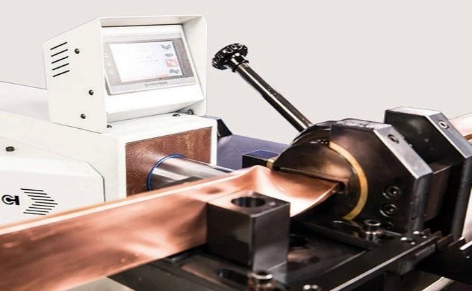
The machine structure is designed to support stable bending during repeated production. However, continuous performance should be verified using representative materials, drawings and tooling rather than assumed from machine construction alone.
During FAT or production testing, record the setup time, complete cycle time, number of operators, measured bending results, accepted parts, rejected parts and any corrections made during the batch. Compare the first, middle and final workpieces to evaluate repeatability over continuous operation.
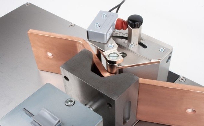
Stored programs can reduce repeated parameter entry when the same drawing, material and tooling are used again. However, program recall does not replace verification of the drawing revision, material batch, tooling and first finished part.
After changing the material grade, temper, thickness, tooling radius or bend direction, inspect and approve the first part before continuing batch production.
Depending on the approved configuration, CNC may control the bending stroke, target angle, servo backgauge position or stored production recipe. Confirm every controlled axis and remaining manual step in the quotation.
It may process both materials with approved tooling and settings. Confirm the material grade or alloy, temper, width, thickness, bend direction, inside radius and surface requirements separately.
No. Servo positioning accuracy describes movement of the positioning axis. Finished-angle accuracy must be measured after the workpiece is released and can also be affected by material, tooling and springback.
This depends on the approved machine capacity and tooling. Flat- and vertical-bending limits should be confirmed separately because they may differ significantly.
Not necessarily. A CNC or servo-positioning system may control selected positions while loading, alignment and unloading remain manual. Confirm the exact automation boundary for the quoted machine.
Provide the material grade or alloy, temper, width × thickness, raw-bar length, bend direction, angle, inside radius, minimum short-leg length, bend sequence, required tolerance, batch quantity, local voltage and dimensioned drawings.

