
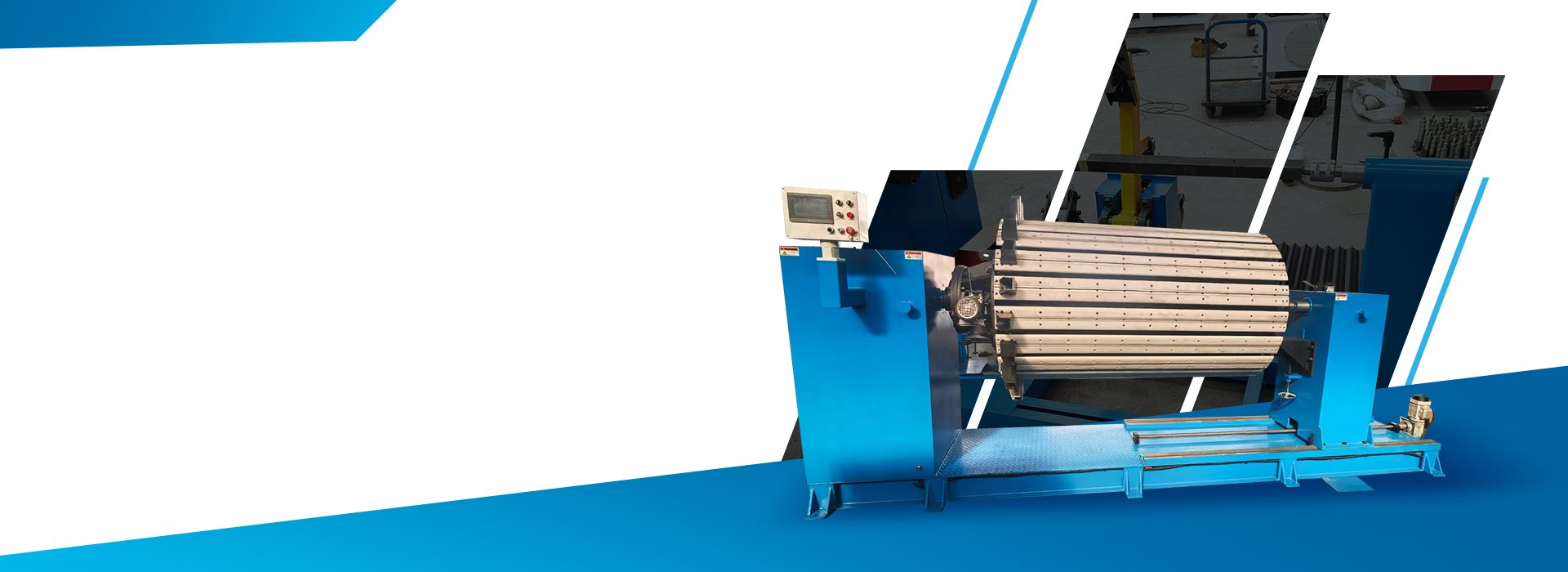
What Does a Transformer Rewinding Project Require?
A transformer rewinding project begins with the accurate recording of the original winding rather than with machine operation.
Before the failed coil is removed, the repair team should document the original conductor material and dimensions, turn count, winding direction, layer structure, insulation arrangement, internal and external dimensions, axial height, lead positions and mandrel or former structure.
The replacement winding should then be reviewed against the approved repair specification. The winding machine provides the mechanical rotation, torque, counting and support required to produce the new coil, while the repair drawing and process specification define the finished result.
Transformer Rewinding Machine Configurations
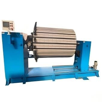
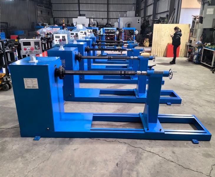
Designed for replacement coils requiring horizontal mandrel support and controlled winding. Confirm the coil-and-mandrel load, shaft interface, spindle torque and effective winding length.
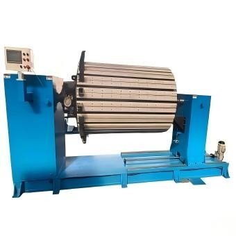
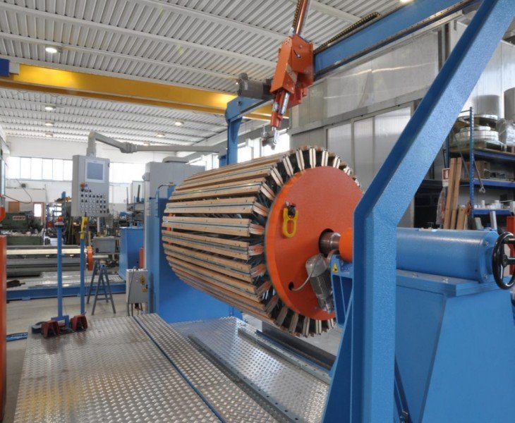
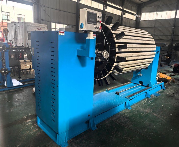
Suitable for larger transformer repair coils and replacement windings. Confirm the winding load, load distribution, spindle torque, tailstock support and braking requirements.
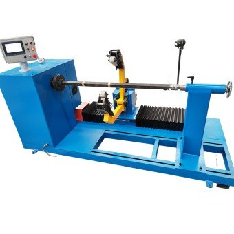
Suitable for repair projects requiring clockwise or counterclockwise winding. Confirm the winding direction, turn-counting method, motor braking and power-off memory.
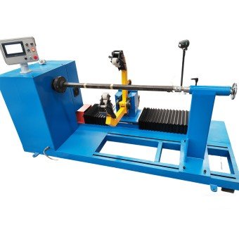
Configured for different coil dimensions, conductor specifications, insulation structures and mandrel designs. Send the original coil data and replacement-coil drawing for review.
Horizontal Transformer Rewinding Machine Project Requirements
| Item | Supplied Project Requirement | What It Affects | Final Confirmation |
|---|---|---|---|
| Winding Arrangement | Horizontal | Coil loading, mandrel support and workshop layout | Confirm the approved machine layout |
| Intended Application | Large-capacity laminated and replacement coils | Machine structure and winding-process suitability | Confirm using representative coil drawings |
| Requested Maximum Winding Load | ≥2,000 kg | Frame strength, shaft support, drive torque and braking | Define coil, mandrel and fixture weight in FAT |
| Stated Machine Size | 650 × 3,000 mm | Installation space and material-handling clearance | Confirm complete L × W × H drawing |
| Winding Head Direction | Left side when viewed from the winding station | Operator position and production-line arrangement | Confirm in the approved layout |
| Spindle Speed | 0–70 r/min | Winding speed and process control | Confirm test speeds under agreed loads |
| Reduction Ratio | 7.2 | Output speed and available spindle torque | Confirm reducer model and ratio |
| Drive Method | Direct motor drive to reducer | Transmission structure and maintenance requirements | Confirm drive-system configuration |
| Spindle Center Height | 1,100 mm above floor level | Mandrel loading and operator working height | Verify by dimensional inspection |
| Tailstock Telescopic Stroke | 0–100 mm | Mandrel clamping and axial adjustment | Verify stroke and locking during FAT |
| Motor Power | 5.5 kW | Drive capacity and electrical demand | Confirm motor nameplate data |
| Motor Brake | Required | Controlled stopping and spindle holding | Test under agreed load and speed |
| Spindle-to-Cabinet Distance | 1,000–1,500 mm | Coil clearance and operator access | Confirm according to the workshop layout |
| Spindle Specification | 40 × 40 mm heat-treated square shaft | Mandrel connection and load transmission | Confirm material, heat treatment and dimensions |
| Effective Spindle Length | 1,500 mm | Maximum available mandrel and coil length | Confirm against the customer’s coil drawing |
| Rear Spindle Thread | M40, with nut and wrench | Mandrel locking and installation | Verify thread, nut and supplied wrench |
| Working Voltage | AC 380 V ±10% | Electrical compatibility | Confirm phase, frequency and local power supply |
| Maximum Spindle Torque | ≥400 N·m | Heavy-coil starting and winding capability | Define torque test method and load condition |
| Turn-Count Range | 0–9,999 turns | Supported winding-program range | Verify full display and counting range |
| Turn-Count Functions | Forward/reverse counting and power-off memory | Reversible winding and interrupted-production recovery | Test forward, reverse and power-restoration functions |
| Stated Counting Criterion | 0.1 turn; definition to be confirmed | Turn-count display and acceptance accuracy | Clarify whether it means resolution or accuracy |
| Speed Regulation | Variable-frequency speed control | Speed adjustment for different coils and conductors | Confirm inverter model and operating controls |
| Auxiliary Supply | Front 220 V auxiliary socket | Connection of auxiliary tools or equipment | Confirm socket type, rating and protection |
| Tension Controller | Near the winding head; final position confirmed after contract | Conductor tension operation and accessibility | Confirm control method, range and installation position |
| Machine Color | Confirmed after contract | Appearance and customer factory standard | Record the approved color code in the order |
The table reflects a supplied horizontal rewinding-machine project requirement and should not be interpreted as the standard specification of every machine. Final guaranteed values, complete dimensions, safety equipment, tension configuration and FAT criteria must be confirmed in the approved technical quotation.
Functions Defined in the Supplied Project Requirement

The specified spindle speed range is 0–70 r/min. Operating speed should be selected according to the coil and mandrel load, conductor specification, shaft balance and winding-quality requirement.

The spindle supports forward and reverse rotation. The required winding direction should be confirmed from the approved replacement-coil drawing before production.

The specified counter supports forward and reverse counting, a range of 0–9,999 turns and power-off memory. The meaning and FAT method for the stated 0.1-turn criterion should be confirmed in the technical agreement.

The project requirement includes motor braking and spindle self-locking after stopping. The FAT should test controlled stopping under an agreed load and speed.
Tension and Guiding Must Be Confirmed by Conductor
The supplied project requirement identifies a tension controller near the winding head but does not define its control method, adjustable range or feedback system.
Confirm whether the proposed tension system is manual, mechanical, magnetic-powder, pneumatic, servo-controlled or another approved configuration.
The selected system should be reviewed according to the conductor material, cross-section, insulation, reel condition, guiding method, winding speed and coil structure. Verify the configuration using representative conductor during FAT.
What Original Coil Data Should Be Recorded?
| Information | Details to Record | Used to Confirm |
|---|---|---|
| Winding Data | Turn count, winding direction, taps and lead sequence | Replacement winding plan |
| Conductor and Insulation | Material, cross-section, insulation and layer arrangement | Material, tension and guiding setup |
| Coil Geometry | Inner size, outer size, axial height and layer dimensions | Mandrel and machine clearance |
| Acceptance Requirements | Lead positions, dimensional tolerances and inspection method | Sample winding and FAT |
Record and approve the original winding data before removing the failed coil. Missing or incorrect design information cannot be recovered by the winding machine.
How to Compare China’s Top Transformer Winding Machine Manufacturers
There is no universally recognized official ranking of China’s top transformer winding machine manufacturers. Published top-10 lists should be used only to create an initial supplier shortlist.
For a transformer rewinding project, compare the actual configuration proposed for your replacement-coil data rather than relying only on brand claims, general product ranges or promotional rankings.
| Comparison Factor | What to Confirm | Evidence to Request |
|---|---|---|
| Rewinding Application | Repair, refurbishment and replacement-coil experience | Actual project photos and sample coils |
| Machine Capacity | Load, speed, torque, shaft and mandrel interface | Signed technical specification |
| Process Functions | Counting, rotation, braking, tension and guiding | Live function demonstration |
| Sample Test | Representative conductor, mandrel and coil drawing | Sample coil and inspection report |
| FAT and Service | Acceptance criteria, documents, warranty and parts | Signed FAT and service scope |
A manufacturer list is only a sourcing reference. Final selection should be based on the approved configuration, representative replacement-coil test, FAT results and contract terms.
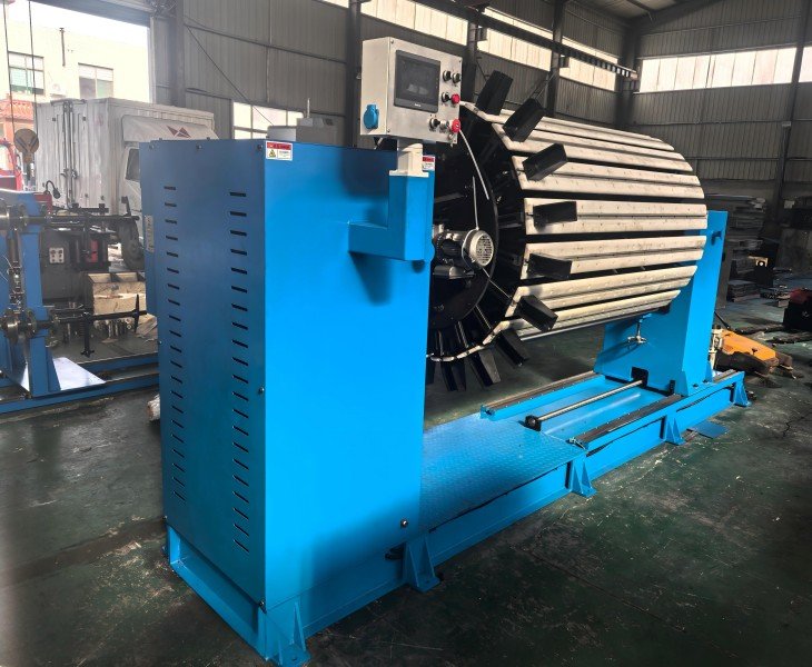
Transformer Coil Rewinding Workflow
1. Record the Original Winding
Document the conductor, number of turns, winding direction, layer structure, insulation, coil dimensions, lead positions and connection sequence before dismantling.
2. Approve the Replacement Drawing
Convert the recorded data into an approved repair or replacement-coil drawing. Any design change should be reviewed by the responsible transformer engineer.
3. Confirm the Machine and Mandrel
Check the replacement-coil weight, mandrel dimensions, shaft connection, available spindle length, required torque and tailstock position against the proposed RX-2 configuration.
4. Prepare the Conductor and Insulation
Confirm conductor material, cross-section, insulation system, reel arrangement, tension method and layer-insulation sequence.
5. Wind the Replacement Coil
Set the winding direction, counter, operating speed and approved process settings. Inspect the first layers before continuing the complete coil.
6. Inspect the Finished Coil
Verify the turn count, coil dimensions, layer structure, insulation placement, lead positions, surface condition and removal from the mandrel.
How Should Replacement Coil Quality Be Verified?
Replacement-coil quality should be evaluated against the approved drawing and winding-process specification rather than general claims such as high precision or stable winding.
Inspect the final turn count, winding direction, coil internal and external dimensions, axial height, layer structure, conductor arrangement, insulation position, lead locations, surface condition and mandrel stability.
For repeated coils, compare samples produced at the beginning, middle and end of the agreed test run. Record the material, machine settings, measuring instruments, acceptance limits and actual results.
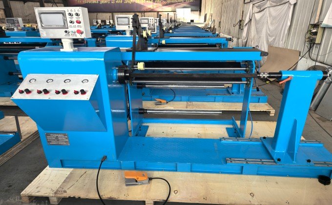
Fenghua’s transformer rewinding machines maintain high rotational speeds during prolonged winding and stable winding quality, allowing your entire production line to meet the demands of large-volume orders.
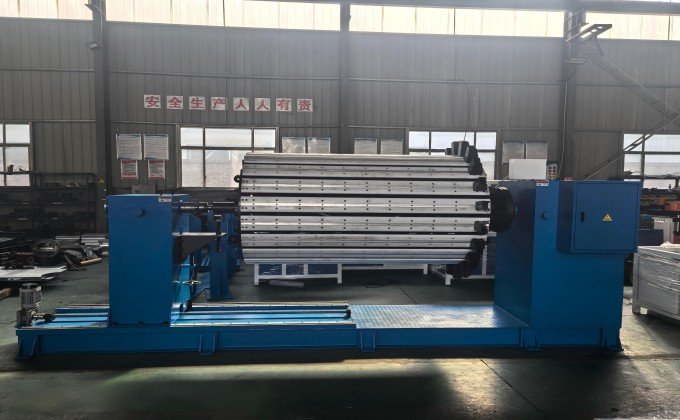
By pre-setting parameters for execution processes, the transformer winding machine entrusts critical winding procedures to the completion, allowing ordinary workers to achieve high-quality winding results.
Transformer winding generally refers to producing coils for a new transformer. Rewinding refers to producing a replacement coil for a repair or refurbishment project after the original winding data has been recorded and approved.
No. Removal, inspection and documentation of the failed winding are separate transformer-repair operations. The machine is used to produce the approved replacement coil.
Record the conductor material and cross-section, turn count, winding direction, layer and insulation structure, coil dimensions, lead positions, taps and connection sequence.
No. Control functions vary by configuration. Variable-frequency speed control, electronic counting or reversible rotation do not automatically mean that the machine includes PLC control, touchscreen operation, automatic traversing or closed-loop tension control.
Compatibility depends on the conductor material, cross-section, insulation, reel arrangement, tension method, guiding system, required torque and coil structure. Each conductor should be reviewed and tested separately.
Inspect the turn count, winding direction, dimensions, layer structure, insulation position, lead locations and surface condition against the approved replacement-coil drawing and FAT criteria.
 Industrial-Grade Durable Rewinding Machine
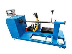 High-Efficiency Transformer Rewinding Machine
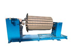 High-Precision Transformer Rewinding Machine
- Automated Transformer Rewinding Machine

