
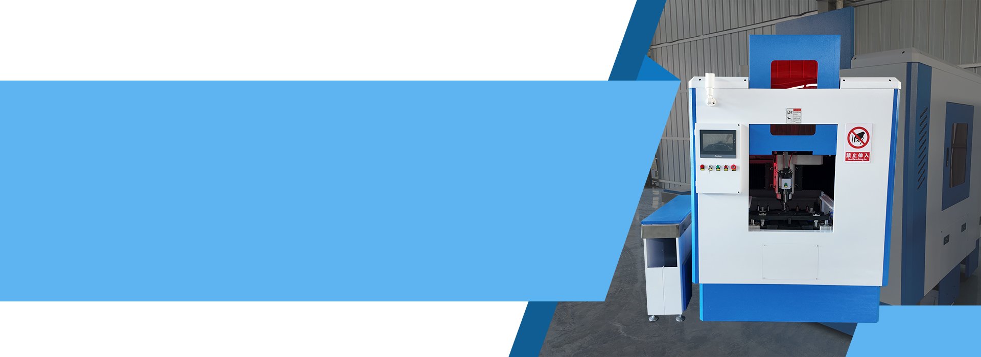
Quick Answer: What Is a Busbar Arc Machining Center?
A busbar arc machining center is a CNC milling machine used to process rounded corners, fillets, chamfers and special profiles at the ends of copper or aluminum busbars. It does not normally bend a straight busbar into a curved conductor. Select the machine according to material, width × thickness, workpiece length, required end profile, radius or chamfer, tooling, clamping, surface requirements and FAT samples.
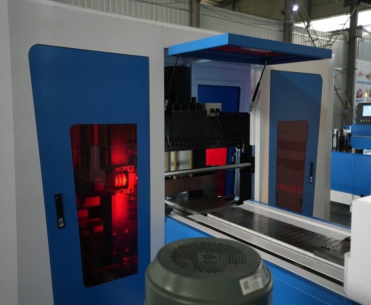
Busbar Arc Machining Center Manufacturer for End-Profile Processing
FengHua configures busbar arc machining equipment according to the finished end profile rather than only the requested radius. Before quotation, the engineering review should confirm the material grade or alloy, temper, width × thickness, minimum and maximum workpiece length, rounded-corner radius, chamfer angle, profile drawing, surface requirements, burr limit and batch quantity.
The technical quotation should identify the exact machine model, supported material range, CNC axes, spindle configuration, tool holder, included cutters, optional tools, clamping method, chip and coolant system, safety configuration, FAT samples, documentation, warranty and recommended spare parts.
Fenghua CNC's Arc Machining Center Products
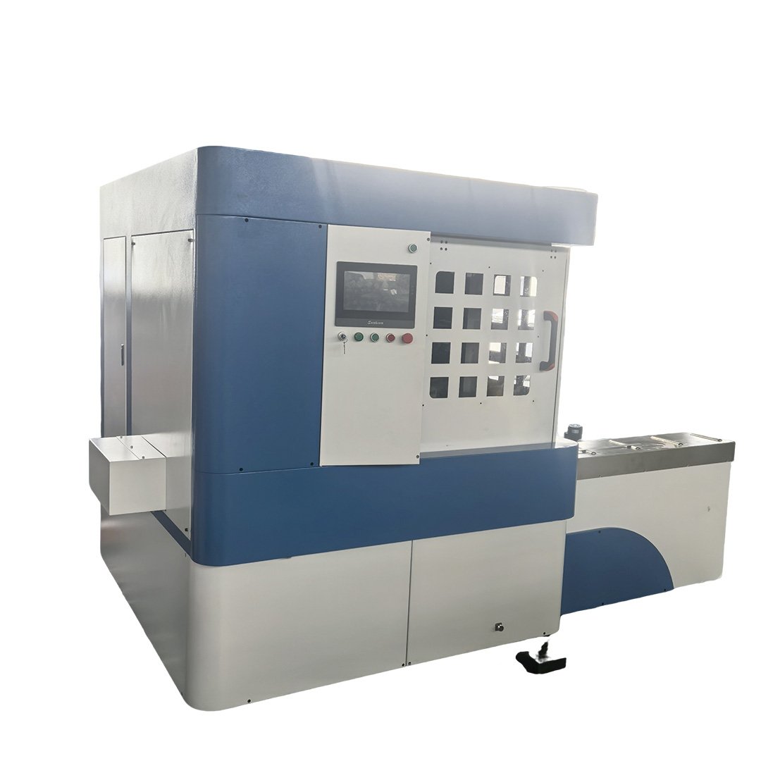
For milling rounded corners and fillets on cut copper or aluminum busbar ends. Confirm the material range, minimum workpiece length, required radius, clamping method and finished contour against your drawing.
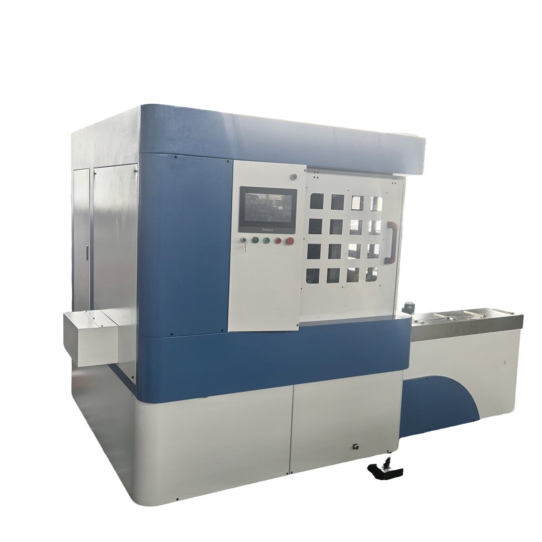
For straight, angled or drawing-specific chamfers on busbar ends and edges. Confirm the chamfer geometry, cutter type, tool holder, burr requirement and surface condition.
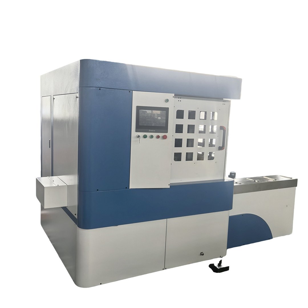
For repeated production involving several approved corner radii or end profiles. Confirm the tool quantity, tool-change method, program recall, tool calibration and model-change time.
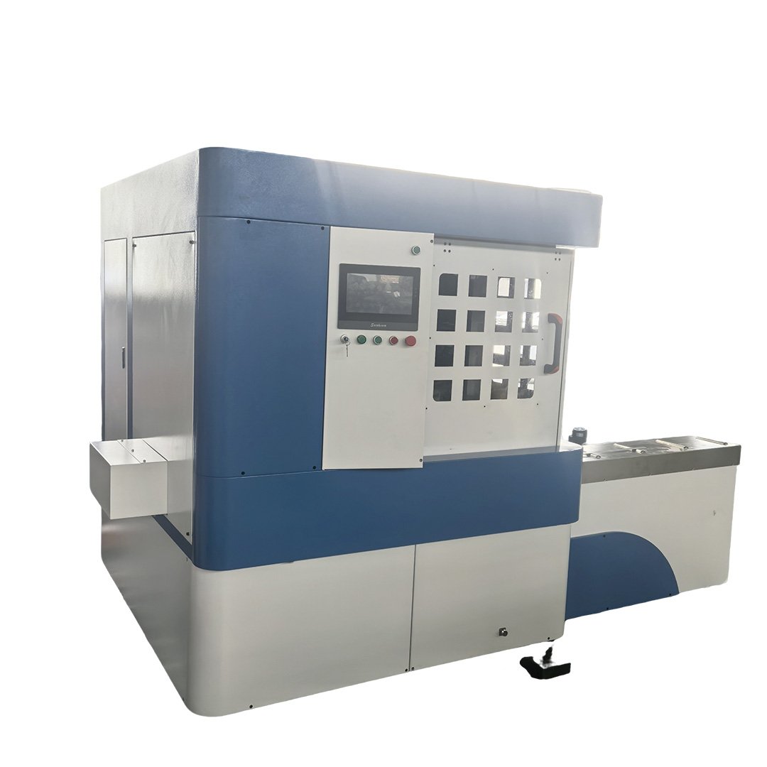
For long, short, wide or non-standard busbars requiring customized fixtures, material supports, cutting tools or special end profiles. Final feasibility is confirmed through drawing review and FAT samples.
Which Busbar Arc Machining Configuration Should You Choose?
| Production Requirement | Starting Configuration | Main Check |
|---|---|---|
| Standard rounded corners | End arc milling machine | Radius, material range and clamping |
| Straight or angled chamfers | CNC chamfering machine | Chamfer geometry and cutter |
| Several recurring end profiles | Multi-tool CNC configuration | Tool change and program recall |
| Non-standard or long workpieces | Customized configuration | Fixture, support and FAT sample |
The correct configuration is determined by the complete end-profile drawing, not only by one radius value.
What Should You Confirm in a Busbar Arc Machining Center?

Confirm copper or aluminum grade, temper, width, thickness, minimum length, maximum length and whether long workpieces require external support.

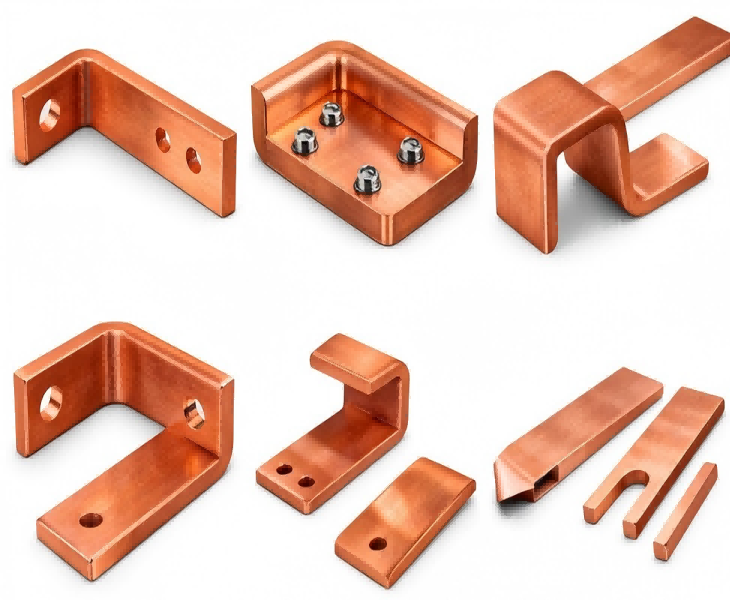
Provide the complete end drawing, including corner radius, chamfer angle, chamfer width, straight sections, transitions and dimensional tolerances.

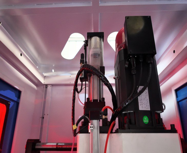
Confirm spindle speed and power, tool-holder standard, controlled axes, axis travel, included cutters, tool-change method and replacement-tool availability.

Confirm datum positioning, clamping method, chip collection, coolant or lubrication, surface marks, burr limit and finished-profile inspection.
How Should the Finished Arc or Chamfer Be Verified?
Do not evaluate the machine only from the programmed tool path or controller display. Inspect the finished busbar after unloading and cleaning. The acceptance method should identify the drawing datum, required radius or chamfer, contour tolerance, surface condition and burr limit.
For rounded corners, use a radius gauge, profile template, contour measurement system or coordinate measurement method agreed before FAT. For chamfers, record the chamfer width, angle, symmetry and transition to the straight edge.
| Check | What to Measure |
|---|---|
| Geometry | Radius, chamfer angle and profile dimensions |
| Position | Profile location from the drawing datum |
| Surface | Tool marks, scratches and edge damage |
| Consistency | Multiple consecutive finished parts |
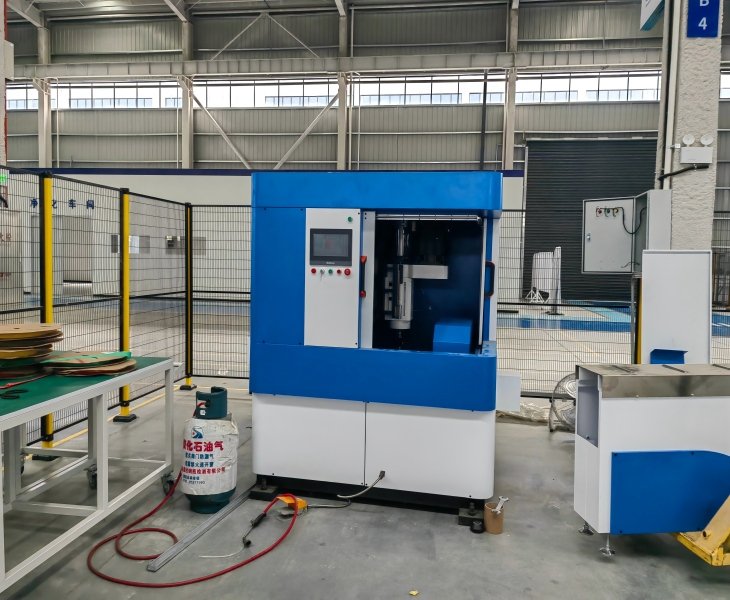
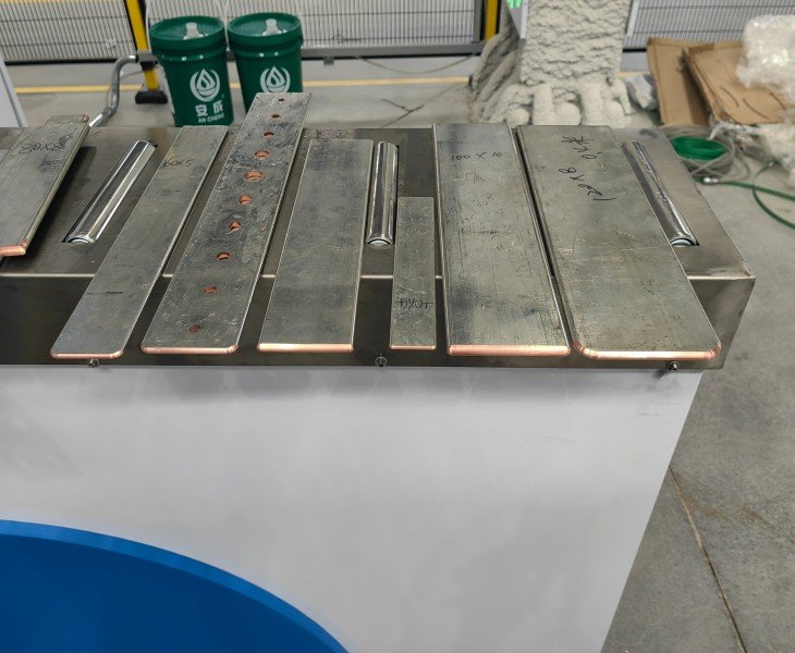
How Should Batch Repeatability Be Tested?
Repeatability should be verified by machining several consecutive parts using the same material, program, fixture and tooling. Measure the first, middle and final samples rather than relying on one successful part.
Record profile dimensions, surface condition, burrs, tool wear, setup changes and any correction made during the test. Do not claim that accuracy will never decrease regardless of batch quantity.
How Are Different Radii and Chamfers Produced?
Different radii and chamfers may require different forming cutters, milling tools, tool offsets, fixtures or programs. Program recall can reduce repeated data entry, but it does not prove that every profile can be produced without a tool or fixture change.
The quotation should state which profiles use the same cutter, which require another cutter, whether tool changes are manual or automatic and how the first part is inspected after changeover.
How to Compare China’s Top Busbar Arc Machining Center Manufacturers
There is no single official ranking that certifies the ten best busbar arc machining center manufacturers in China. A Top 10 list should be used as a supplier-research starting point rather than proof of machine quality, accuracy or service capability.
Compare the exact proposed model, material and workpiece range, CNC axes, spindle, tooling, clamping, profile samples, FAT records, documentation, warranty and spare-parts support.
| Supplier Check | Evidence |
|---|---|
| Exact Model | Nameplate and configuration sheet |
| Capacity | Material, width, thickness and length |
| CNC and Tooling | Axes, spindle, holder and cutters |
| Samples | Radius, chamfer, surface and repeatability |
| Support | FAT, documents, warranty and spare parts |
How Do Workpiece Length and Clamping Affect Machining?
Short workpieces may not provide enough clamping area, while long busbars may require roller tables or external supports. Wide or heavy bars can also affect loading, alignment and fixture clearance.
Confirm the minimum clampable length, maximum supported length, positioning datum, support arrangement, allowable overhang and whether the workpiece must be reversed to machine both ends.
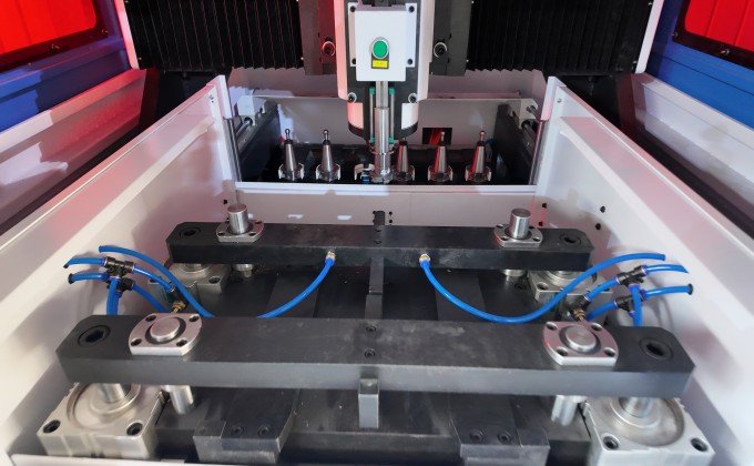
Do not compare machines only by spindle speed or one cutting pass. Complete cycle time should include loading, positioning, clamping, tool selection, milling, tool return, unclamping, chip cleaning, unloading and inspection.
For repeat orders, record tool life, cutter-replacement time, setup time, conforming parts, rejected parts and any surface-quality changes during the batch.
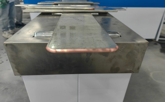
Special profiles may combine straight sections, several radii, angled chamfers and transitions. Review cutter access, fixture interference, clamping area, machining sequence and whether the part must be repositioned or reversed.
Send one standard drawing, one maximum-size drawing and one complex drawing before quotation. Unsupported profiles and required secondary operations should be identified in writing.
It mills rounded corners, fillets, chamfers and special profiles on the ends or edges of copper and aluminum busbars. It does not normally bend a straight busbar into an arc-shaped conductor.
It may process several radii using approved cutters, tool offsets, fixtures and programs. Confirm which profiles use the same tool and which require a tool or fixture change.
It may process both materials when the machine, cutter, feed setting and clamping method are approved. Confirm the material grade or alloy, temper, width, thickness and surface requirements separately.
No. Axis positioning describes machine movement. Finished-profile accuracy must be measured on the completed and cleaned workpiece and can also be affected by the cutter, clamping, tool wear and material movement.
This depends on the machine structure, workpiece length, fixture and tool access. Some parts may need to be reversed or repositioned. The required sequence should be demonstrated during FAT.
Provide the material, grade or alloy, temper, width × thickness, minimum and maximum length, radius, chamfer angle, end-profile drawing, surface requirement, burr limit, batch quantity, local voltage and CAD or PDF files.

