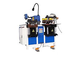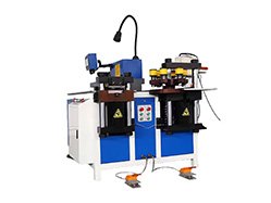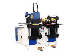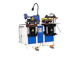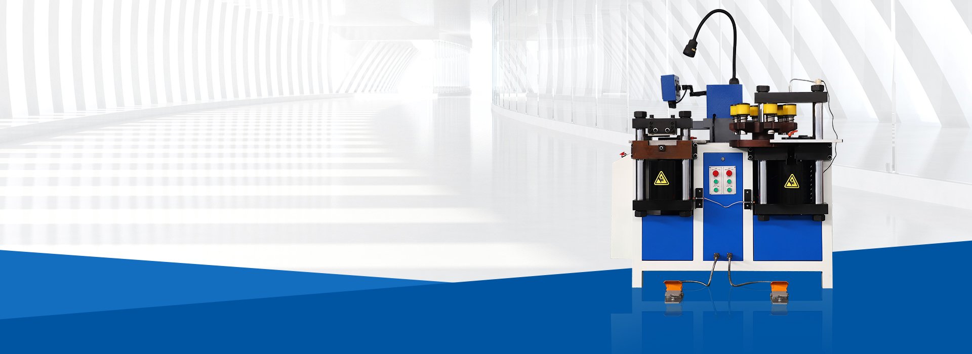
Copper Busbar Machine Manufacturer for Drawing-Based Production
FengHua configures copper busbar machines according to your finished-part drawings rather than only the nominal machine force. Before quotation, the engineering review should confirm the copper grade and temper, regular and maximum width × thickness, raw-bar length, hole and slot layout, finished cutting length, bending direction, inside radius, minimum short-leg length, required tolerances and batch mix.
The technical quotation should identify the exact model, capacity of each processing station, positioning method, included and optional tooling, material-handling requirements, electrical configuration, FAT samples, documentation, warranty scope and recommended spare parts.
Fenghua Copper Busbar Machines
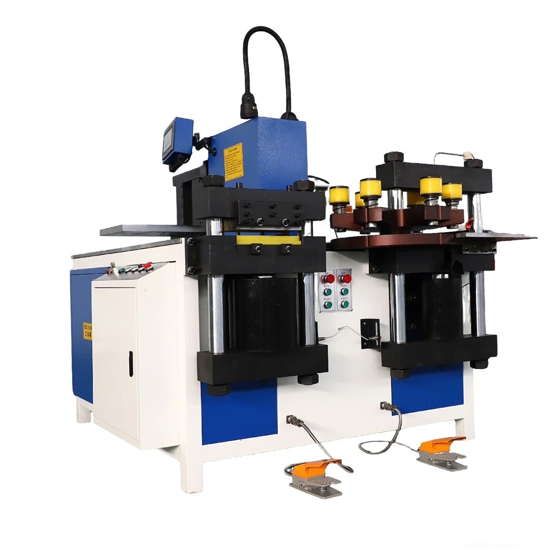
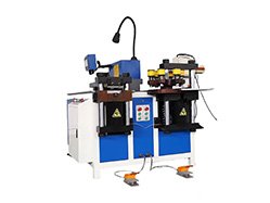
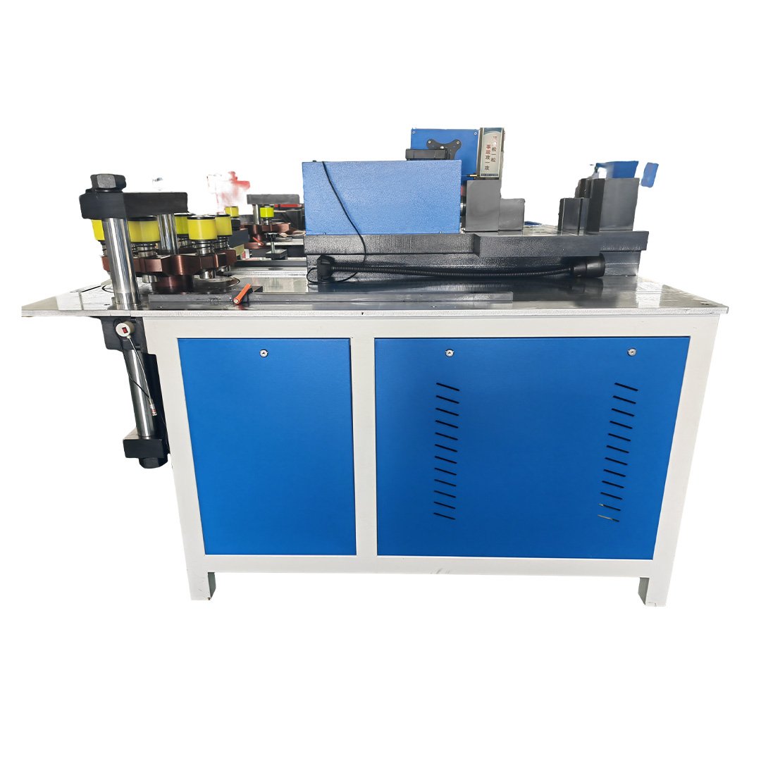
A compact punching, cutting and bending configuration with a published overall processing reference of 160 × 16 mm, a Ø4.3–34 mm punch range and 350 kN punching, bending and cutting force.
- Maximum published size: 160 × 16 mm
- Punch range: Ø4.3–34 mm
- Process force: 350 kN
- Motor configuration: 3 × 4 kW
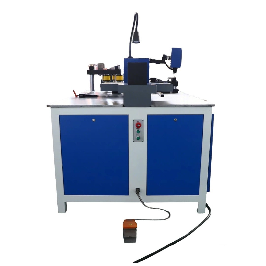
A medium-capacity punching, cutting and bending configuration with a published overall processing reference of 260 × 16 mm, a Ø4.3–34 mm punch range and 500 kN punching, bending and cutting force.
- Maximum published size: 260 × 16 mm
- Punch range: Ø4.3–34 mm
- Process force: 500 kN
- Motor configuration: 3 × 5.5 kW
Strict requirements on hole spacing, bending angles, and busbar cutting dimensions ensure smooth connection of each busbar during subsequent assembly.
- Maximum published size: 300 × 20 mm
- Punch range: Ø4.3–34 mm
- Process force: 800 kN
- Motor configuration: 3 × 7.5 kW
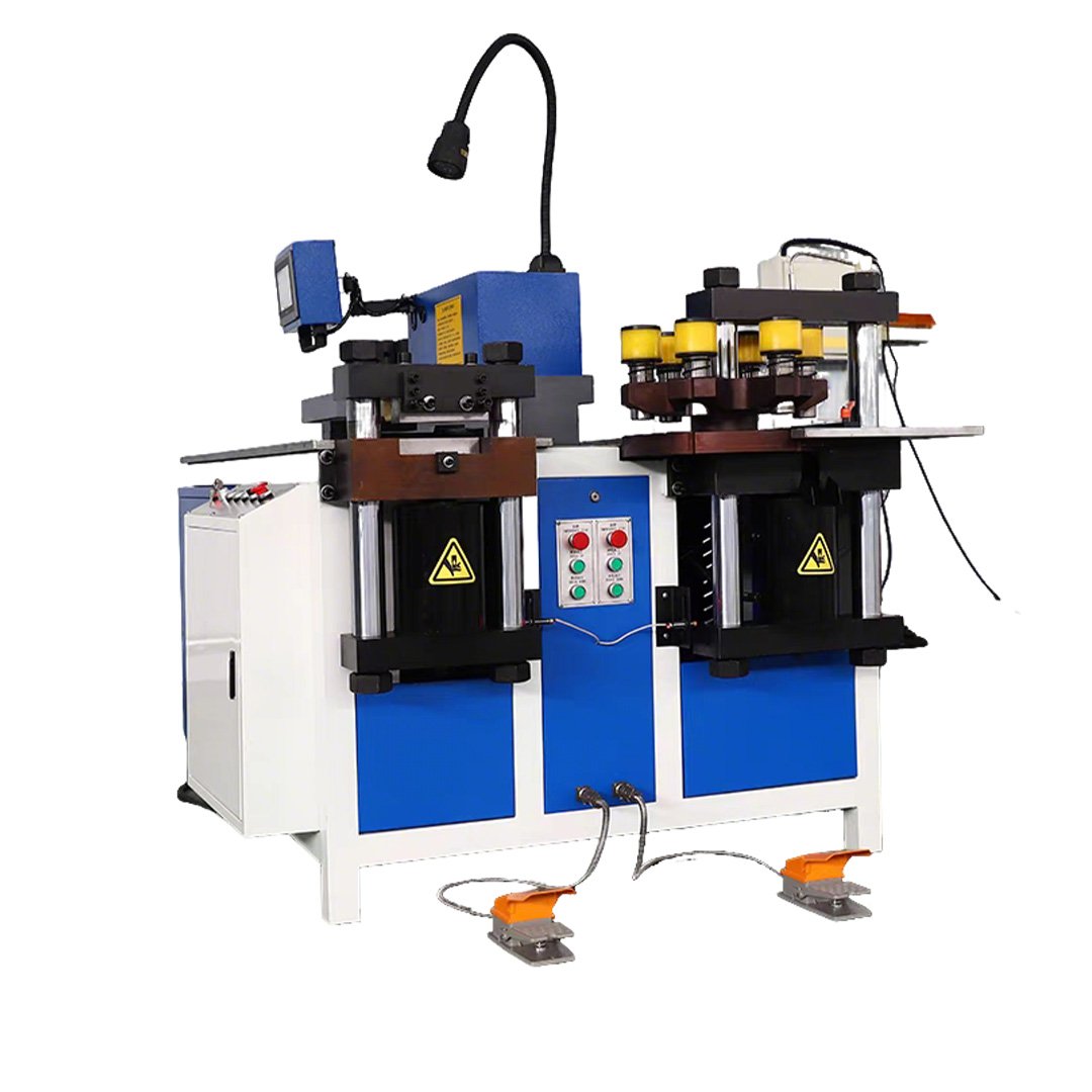
For projects requiring servo positioning, special punching dies, customized bending tools, alternative electrical standards, material-support systems or drawing-based FAT. Final parameters are defined in the approved technical quotation.
Quick Answer: How Should You Select a Copper Busbar Machine?
Select a copper busbar machine according to your drawings, copper grade and temper, maximum width × thickness, raw-bar length, punching, cutting and bending requirements, finished-part tolerances, batch mix, operator requirements and accepted parts per shift. Verify station-specific capacity, controlled axes, tooling, complete cycle time, handling limits, footprint, technical support, total cost and FAT evidence. Do not compare machines only by tonnage, catalogue maximums or the word “CNC.”
Which MX-Series Copper Busbar Machine Should You Choose?
| Production Requirement | Starting Model | Main Check |
|---|---|---|
| Overall sizes within 160 × 16 mm | GJBM-303 | Capacity of each station and required tooling |
| Overall sizes up to 260 × 16 mm | GJBM-503 | Hole range, bend geometry and cutting requirement |
| Overall sizes up to 300 × 20 mm | GJBM-803 | Maximum-size sample and material handling |
| Repeated positioning requirements | Approved MX model + servo option | Positioning range versus finished-part tolerance |
These are starting references based on the uploaded model-level specifications. Final model selection requires separate confirmation of punching, cutting, flat-bending and vertical-bending capacity.
What Should You Confirm in a Copper Busbar Machine?

Confirm punching, cutting, flat-bending and vertical-bending capacity separately. A model-level maximum width and thickness does not automatically apply to every station, die and workpiece geometry.

Separate positioning accuracy, repeat positioning accuracy, hole-position tolerance, cutting-length tolerance and released bending-angle tolerance. These values describe different parts of the process.

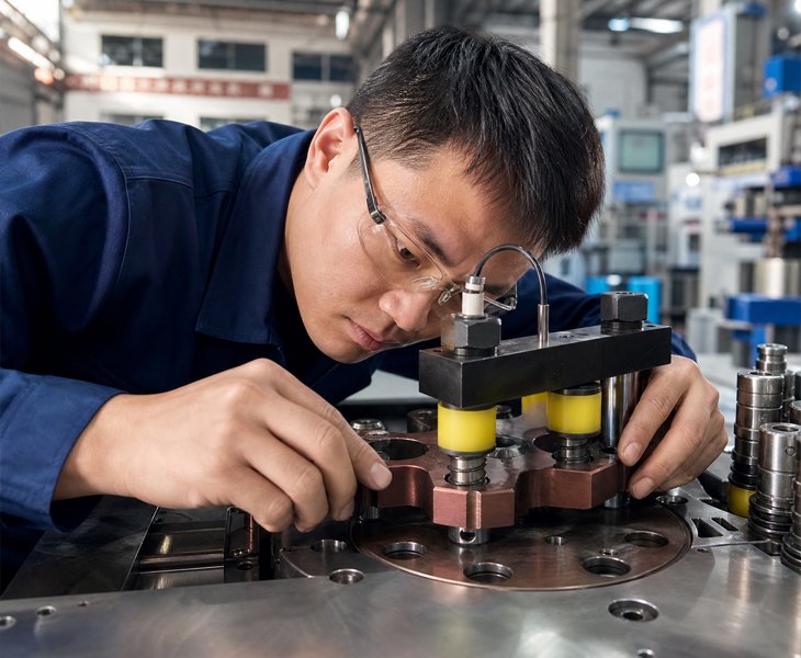
Confirm standard punching dies, special slots, cutting tools, flat-bending dies, vertical-bending tools, replacement lead time and changeover requirements

Evaluate loading, positioning, transfer between stations, tool adjustment, processing, unloading and inspection. Hydraulic speed alone does not represent accepted parts per shift.
How Should Positioning and Finished-Part Accuracy Be Verified?
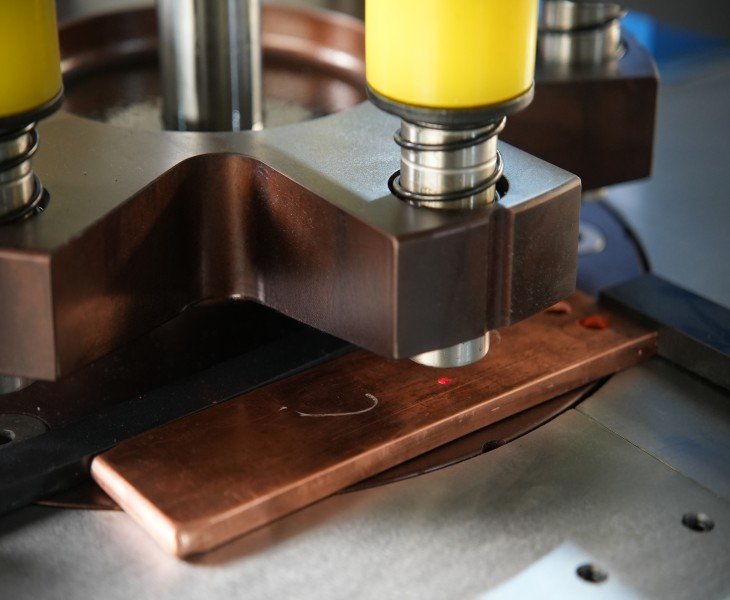
Positioning accuracy describes how closely the positioning system reaches a commanded location. Finished-part accuracy must be measured after punching, cutting or bending and can also be affected by tooling, material movement, springback, operator setup and workpiece support.
For FAT, identify the drawing datum and record hole coordinates, cutting length, released bend angle, short-leg dimensions and repeatability over multiple consecutive parts. Do not use a positioning-system value as a universal finished-part tolerance.
How Should Production Capacity Be Verified?
Do not compare copper busbar machines using hydraulic force or single-stroke speed alone. Complete cycle time should include material loading, positioning, transfer between stations, tooling adjustment, punching, cutting, bending, unloading and inspection.
During a supplier test, record the drawing, material, number of operators, setup time, complete cycle time, accepted parts, rejected parts and any manual repositioning.
When Does a 3-in-1 Machine Reduce Material Handling?
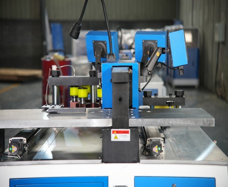
A 3-in-1 copper busbar machine places punching, cutting and bending functions within one machine area, which can reduce transfers between separate machines. However, this does not automatically mean that every part is completed without repositioning or manual handling.
Confirm the station layout, workpiece-transfer sequence, datum retention, material-support method, operator requirements and whether each station can operate independently for the approved model.
Which Copper Busbar Machine Configuration Fits Your Application?
| Application | Typical Requirement | Main Check |
|---|---|---|
| Switchgear and Electrical Panels | Mixed drawings and repeated connection holes | Hole layout, bend sequence and assembly tolerance |
| Transformer Manufacturing | Wider, thicker or longer conductors | Material handling and maximum-size test |
| Busduct and Busway | Repeated conductor profiles | Finished length and double-end geometry |
| Energy Storage Cabinets | Compact and changing parts | Short-part handling and surface protection |
How to Compare China’s Top 10 Busbar Machine Manufacturers
A China Top 10 busbar machine manufacturer list should be used as a supplier-research starting point rather than proof of machine quality, processing accuracy or service capability.
For a copper busbar machine project, compare the exact proposed model, capacity of each processing station, controlled axes, tooling, material handling, representative samples, FAT results, electrical documentation, warranty and spare-parts scope.
| Supplier Check | Evidence |
|---|---|
| Identity | Legal company and factory information |
| Exact Model | Nameplate and configuration sheet |
| Capability | Material, station capacity and tooling |
| Testing | Samples, measurements and FAT |
| Support | Documents, warranty and spare parts |
Control, Tooling and Maintenance Requirements
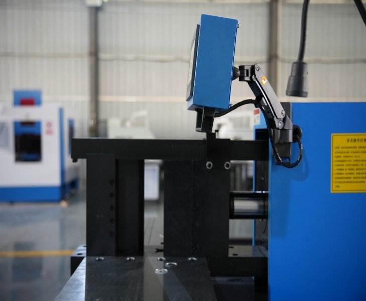
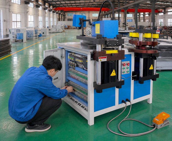
The approved quotation should identify the actual control functions, parameter-entry method, program storage, positioning interface, safety limits, and operator permissions. Do not describe the system as automatically identifying material or adjusting processing force unless these functions are demonstrated on the quoted machine.
The maintenance plan should cover hydraulic oil where applicable, lubrication points, punches and dies, cutting tools, bending tools, sensors, limit switches, electrical components and recommended spare parts.
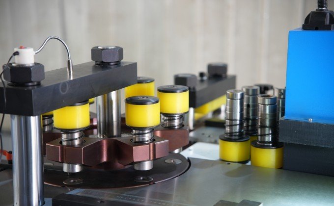
Fenghua’s copper busbar machine is equipped with an advanced intelligent system busbar specifications and adjust the processing sequence and force. It features a visual touch control system for quick parameter setting. Automated control experience, every busbar.

The core components of Fenghua’s copper busbar machines are made of high wear-resistant materials, with a simple and reasonable structural design. Cleaning is very convenient, requiring only simple maintenance, lubrication, and wear inspection, reducing downtime mass-produced products.
The uploaded MX-series source sheet lists punching, cutting and bending functions. Final capability must be confirmed separately for each station, material, die and workpiece drawing.
Not automatically. The uploaded sheet provides overall model-level maximum width and thickness. Punching, cutting, flat-bending and vertical-bending capacity must be confirmed separately.
No. Servo positioning accuracy describes the positioning system. Finished hole locations, cutting length and bending angles must be measured on the completed workpiece using the agreed drawing datum and inspection method.
Provide the copper grade and temper, width × thickness, raw length, hole and slot drawings, cutting length, bend direction, target angle, inside radius, minimum short leg, required tolerances, batch quantity, local voltage and CAD or PDF drawings.