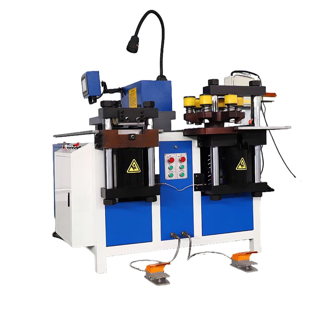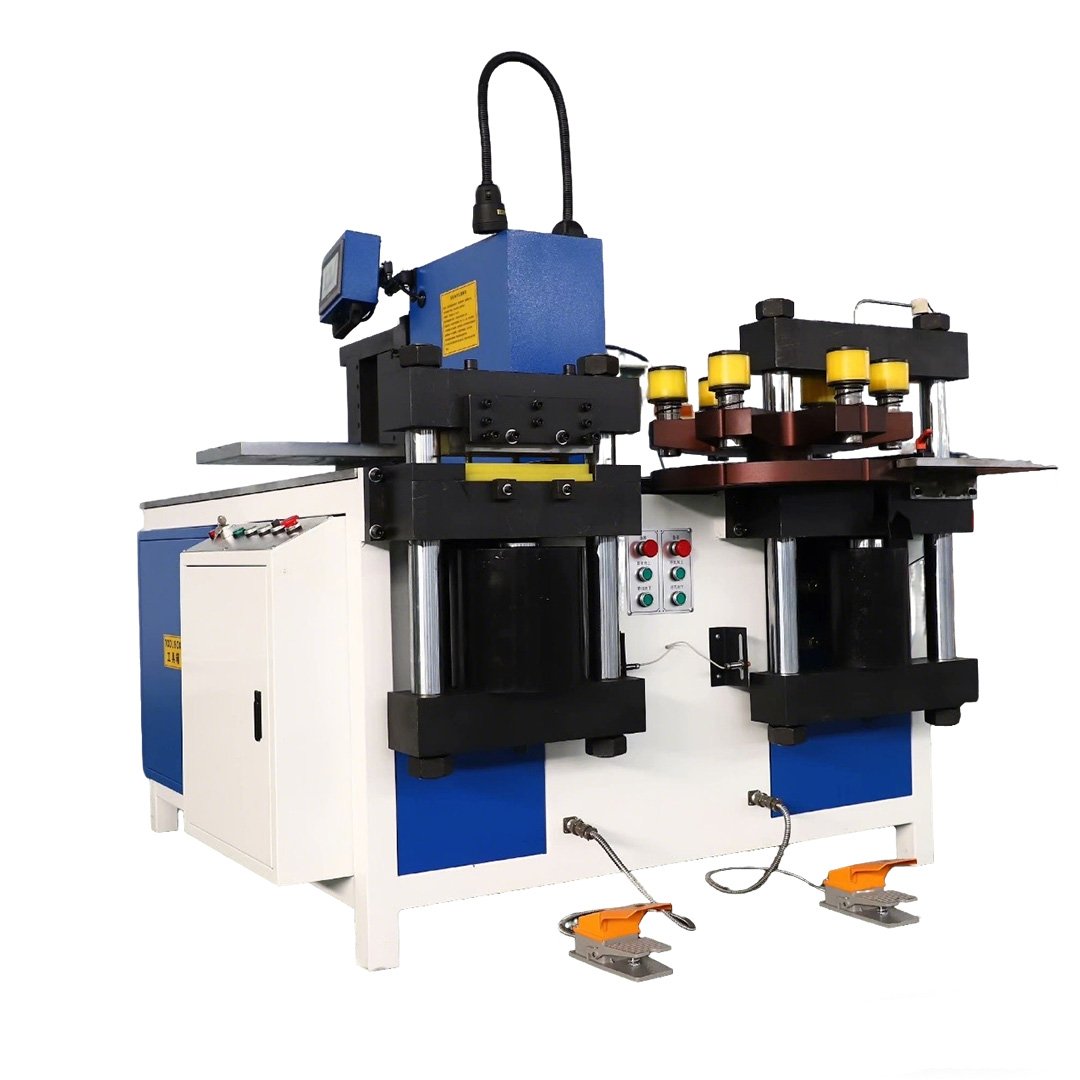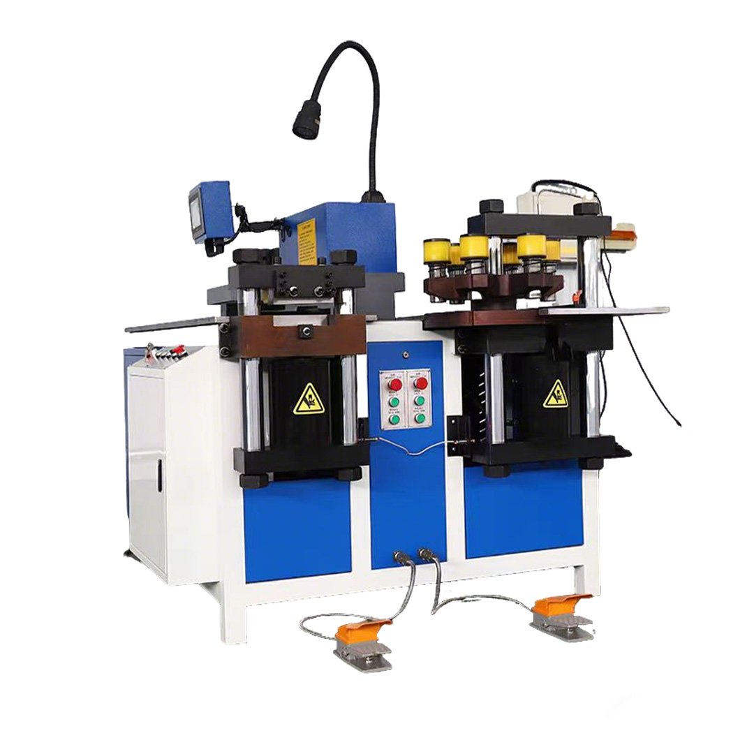
Choose a Busbar Bending Machine for Your Application
FengHua offers hydraulic-drive, CNC-controlled and combined hydraulic/CNC bending configurations for copper and aluminum busbars. Model selection should be based on the material grade and temper, common and maximum dimensions, bending direction, inside bend radius, required tolerances, conforming output per shift and tooling requirements.
Hydraulic and CNC are not opposing machine categories. Hydraulic describes how forming force is generated, while CNC describes how variables such as workpiece position, bending stroke, angle correction or program data are controlled. A machine may combine hydraulic power with CNC control.
A basic hydraulic configuration may be sufficient when operators perform standard bends and manually position or verify the workpiece. CNC-controlled hydraulic or servo configurations become more relevant when drawings recur, parameters must be stored or production requires controlled changeovers. Buyers should confirm exactly which variables are controlled automatically rather than relying on the term “CNC” alone. Send representative drawings before requesting a quotation so that the proposed machine capacity, tooling, bending sequence and possible interference can be reviewed.
FengHua Busbar Bending Machine Configurations
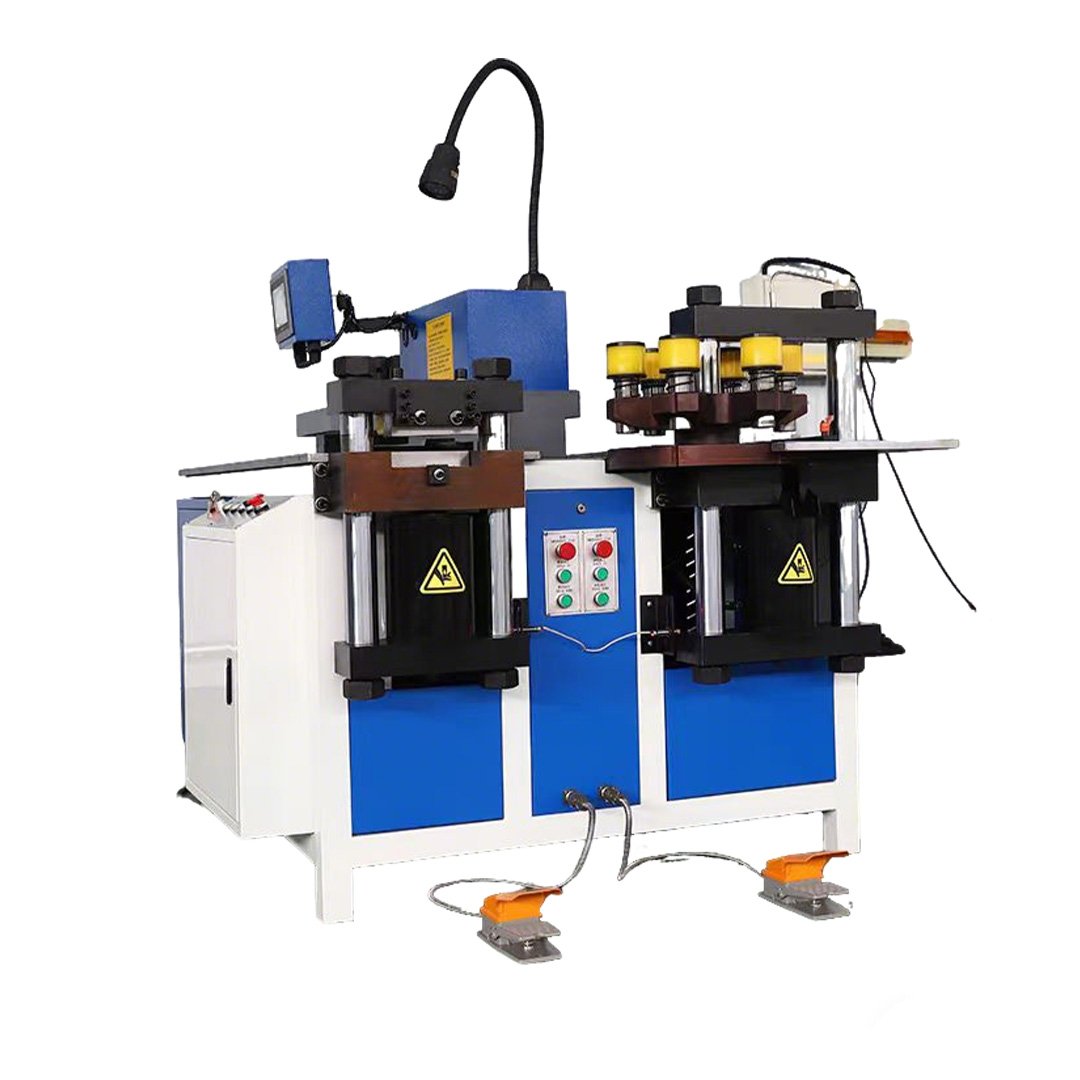
FengHua hydraulic busbar bending machines use hydraulic pressure to form copper or aluminum busbars through matched punches and dies. Compare the nominal bending force, flat- and vertical-bending capacity. Capacity should be confirmed separately for each material, bend direction and tooling configuration.
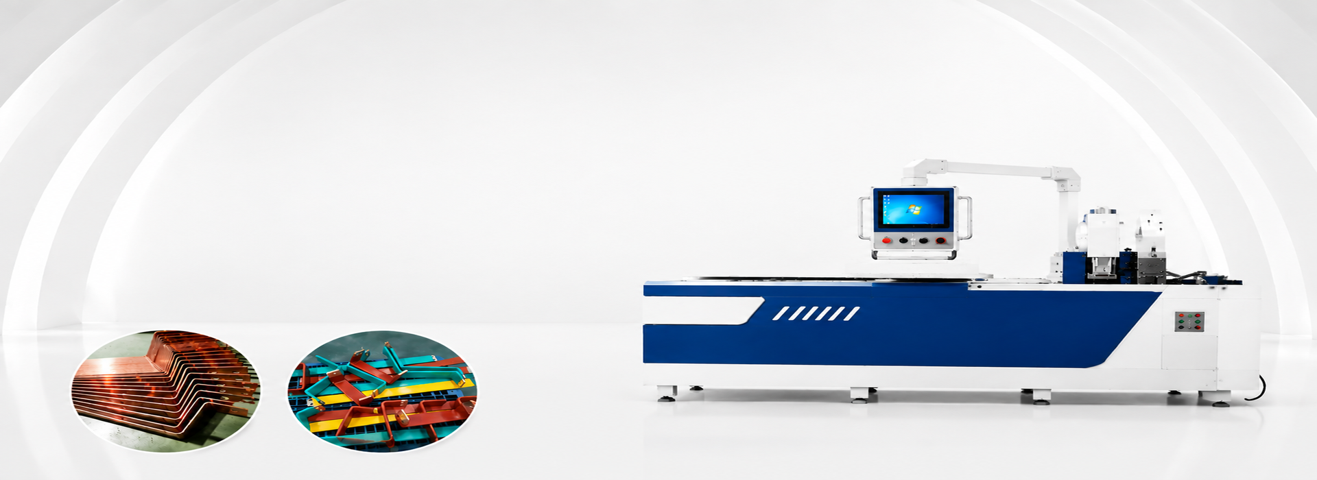
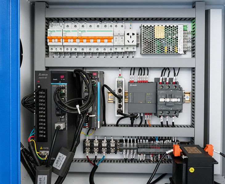
A CNC-controlled busbar bending machine can have selected processing parameters, depending on the model. Confirm whether the controller manages bending stroke, workpiece position, angle correction, or only parameter display. Also verify program capacity, feedback method, repeatability, tooling changeover.
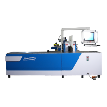
The FengHua heavy-duty busbar bending machine is intended for wider or thicker copper and aluminum busbars that configurations. Review the selected model’s flat-bending limit, vertical-bending limit, nominal force, frame structure, machine weight, and available tooling before confirming suitability.
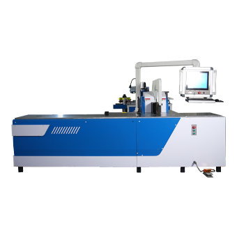
The automatic busbar bending configuration can be controlled according to the selected model. Manual operations include material loading, tooling setup, first-part inspection, and unloading. Confirm the controlled axes, program workflow, angle-correction method, cycle time, and remaining manual operations before ordering.
Information To Confirm Before Selecting A Busbar Bending Machine

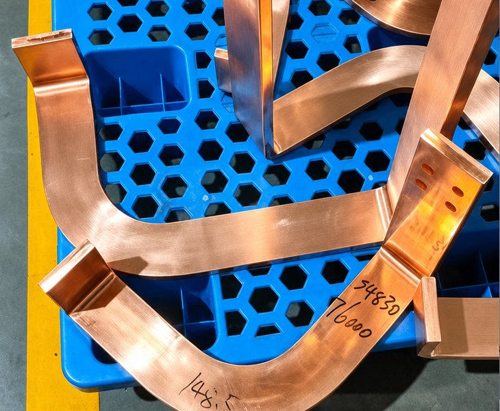
Confirm whether the selected model supports flat bending, vertical bending, offset bending, Z-bending, U-bending, or other special forming structures. Tooling availability: a drawing can be completed.

For the CNC angle-setting method, feedback system, parameter storage, and published repeatability. Ask the supplier to explain how bending angles are measured during sample testing and FAT.

Die package, optional dies, minimum bend radius, vertical-bending tools, special-forming tools, and expected changeover time. Drawing-based tooling should be confirmed.

Confirm emergency stops, guards, interlocks, overload protection, and restart behavior. The quotation and FAT plan should identify which safety functions are included in the selected model.
Basic Hydraulic vs CNC-Controlled Bending
| Selection Factor | Basic Hydraulic Configuration | CNC-Controlled Hydraulic or Servo Configuration |
| Drive and Control | Hydraulic force with manual or basic settings | Hydraulic drive or servo-controlled motion with programmed control |
| Workpiece Positioning | Usually manual unless otherwise specified | Manual, servo or automatic depending on controlled axes |
| Program Storage | Limited or unavailable | Confirm storage, recall and revision functions |
| Angle Control | Confirm stroke setting and measurement method | Confirm feedback, compensation and controlled variable |
| Changeover | More manual adjustment may be required | Can be shorter when approved programs and tooling are prepared |
| Verification | Sample test and measured angle | Sample test, parameter recall and batch consistency |
| Best Fit | Standard or variable low-volume work | Repeated drawings and controlled production changes |
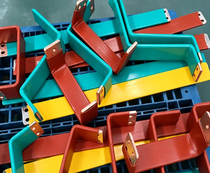
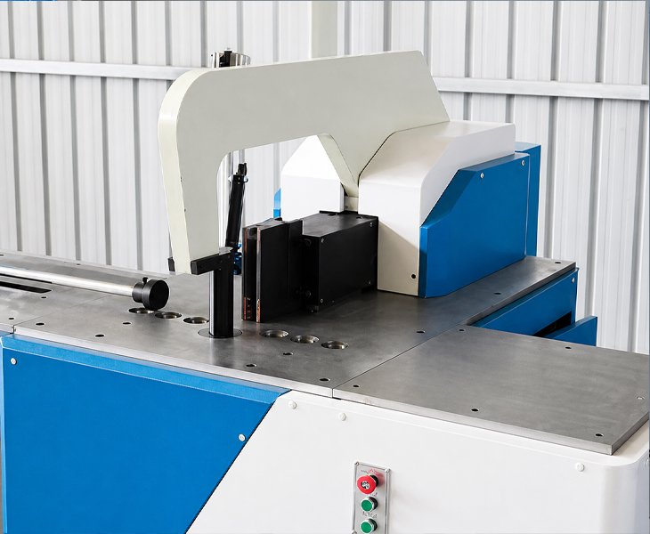
Information Required for Model Selection
| Requirement | Information to Provide |
| Material | Copper or aluminum grade and temper |
| Busbar Size | Common and maximum width, thickness and length |
| Surface | Bare, plated, insulated or coated |
| Bend Types | Flat, vertical, Z-, U-, offset or special bends |
| Bend Radius | Required inside radius |
| Tolerance | Angle, bend-line and dimensional tolerance |
| Production | Batch size and required conforming output |
| Drawings | PDF, DXF, DWG or STEP |
| Power Supply | Voltage, frequency and phase |
| Tooling | Standard and customized die requirements |
Send one common drawing, one maximum-size drawing and one complex drawing. FengHua can review the proposed machine, tooling, bend sequence, interference risks and FAT requirements.
How to Verify Bending Results During FAT
Before ordering, request a bending test using the agreed busbar material, drawing revision, tooling and inspection, released bending angle, bend-line position, inside radius, and dimensional results for final samples. The FAT report should identify the machine model, serial number, material grade, busbar dimensions, tooling, measuring instruments, acceptance tolerances and actual results
Busbar Bending Applications
| Application | Typical Requirement | Verify |
| Switchgear and Control Panels | Repeated bends and multiple cabinet variants | Program recall, bend-line position and changeover |
| Transformers | Wider or thicker conductors | Operation-specific capacity, support and tooling |
| Busduct Systems | Repeated or symmetrical end forming | Double-head capability, spacing |
| Energy Storage and EV Equipment | Compact bends and limited clearances | Bend radius, interference and surface protection |
| Custom Busbar Fabrication | High drawing variety | Tooling flexibility and first-part setup time |
Application names do not model by themselves. Final selection should be based on the actual material, drawing geometry, tolerances, and required output.
Hydraulic describes how bending force is generated, while CNC describes how processing variables are controlled. A CNC bending machine may still use a hydraulic drive. Compare the controlled variables, positioning method, angle feedback, program storage, tooling and sample results rather than selecting by the labels alone.
Some materials, but capacity should be confirmed separately for the required copper or aluminum grade, temper, width, thickness, bend direction, and radius. Request sample processing when cracking, springback, or surface damage is a concern.
Price depends on bending capacity, nominal force, control system, angle-feedback method, positioning functions, tooling, component brands, electrical requirements, and service scope. Compare quotations using the same technical requirement sheet.
Provide the busbar material and grade, common and maximum dimensions, bend types, bend radius, required tolerances, daily output, local power supply and representative drawings.
Agree on the test material, drawings, bend sequence, measuring instruments and acceptance tolerances before FAT. Record the measured angle and dimensions for each representative sample and include the accepted results in the FAT report.