

Quick Answer
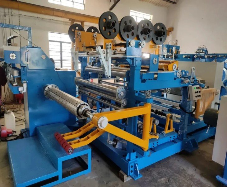
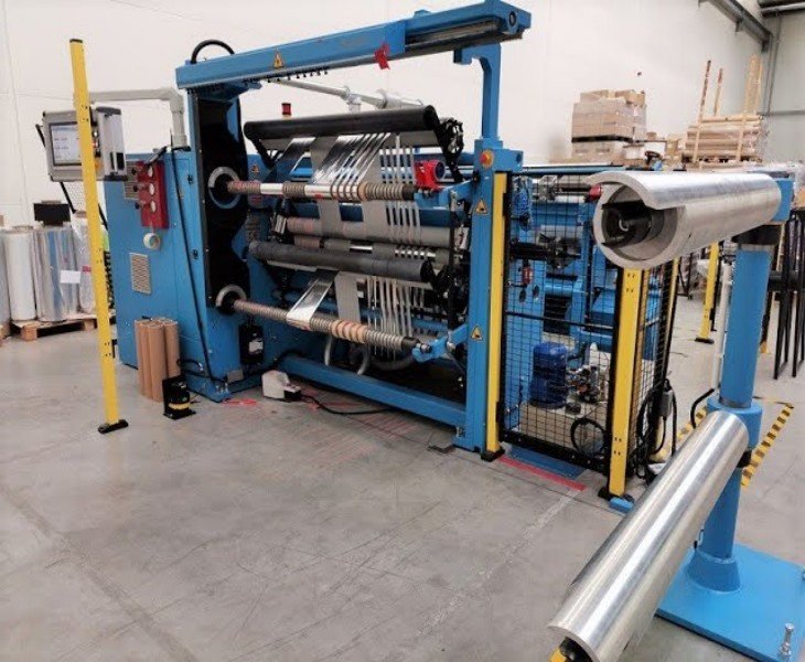
A transformer foil winding machine forms copper or aluminum foil conductors and interlayer insulation into transformer coils, primarily for low-voltage winding applications.
The correct machine depends on the foil material, width, thickness, reel weight, coil dimensions, finished coil weight, insulation specification, decoiling system, tension method, edge-alignment system, welding process and required automation level.
CNC control, automatic foil feeding, closed-loop tension, automatic edge alignment and welding should be confirmed by model and should not be assumed to be included with every machine.
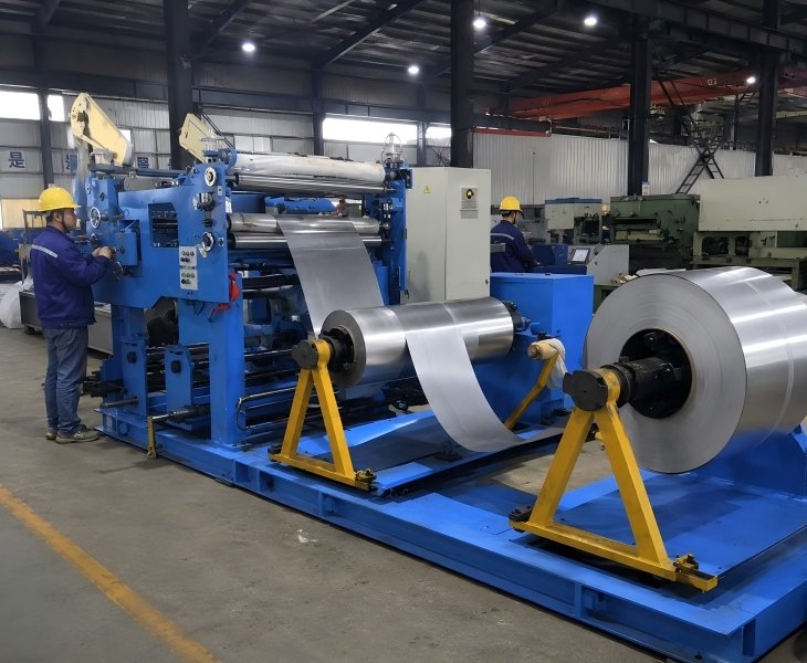
What Is a Transformer Foil Winding Machine?
A transformer foil winding machine winds copper or aluminum foil conductors together with interlayer insulation to produce transformer coils.
Unlike a conventional wire winding machine, a foil winding system normally requires dedicated conductor decoiling, foil tension control, edge-position control, insulation feeding, winding-mandrel support and a suitable conductor-joining process.
The exact configuration varies by coil design. A machine equipped with a CNC controller does not automatically include every feeding, alignment, welding or quality-monitoring function. Each included system should be identified separately in the technical quotation.
Available Transformer Foil Winding Machine Types
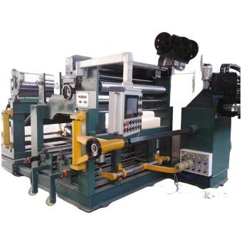
Designed for transformer projects using copper foil conductors. Confirm the copper grade or temper, foil width and thickness, reel weight, coil dimensions, insulation, edge-alignment method and conductor-joining process.
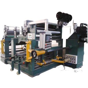
Designed for transformer projects using aluminum foil conductors. Confirm the aluminum alloy or temper, foil dimensions, reel handling, tension settings, edge condition, insulation feeding and joining method.
Intended for low-voltage transformer foil coils. Configuration should be based on conductor material, coil geometry, foil and insulation layers, finished coil weight, winding mandrel and required automation.
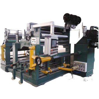
Used when a project requires a specific foil width, coil shape, conductor reel arrangement, insulation system, welding process or production workflow. This is a project review service rather than a separate machine model.
Systems to Confirm Before Selecting a Foil Winding Machine
| System | What It Does | What the Supplier Must Confirm |
|---|---|---|
| Conductor Decoiler | Supports and releases the copper or aluminum foil reel | Number of decoilers, reel dimensions, maximum reel weight, shaft type and braking method |
| Insulation Decoiler | Feeds interlayer insulation during winding | Number of insulation reels, material width, thickness, roll diameter and tension method |
| Foil Tension System | Controls foil stress during feeding and winding | Control principle, adjustable range, feedback method and FAT measurement method |
| Edge-Alignment System | Maintains foil position relative to the coil edge | Manual or automatic correction, sensor type, correction range and response method |
| Winding Spindle and Mandrel | Supports the coil and transfers winding torque | Mandrel shape, dimensions, load, torque, connection and coil-removal method |
| Pressure Roller | Applies pressure to the winding layers when required | Roller width, pressure method, adjustment and applicable coil structures |
| Welding or Joining System | Connects foil to lead bars or joins conductor sections | TIG, cold-pressure or another process, supported materials and included tooling |
| Turn Counting and Control | Manages the winding sequence and recorded turns | Encoder or counter type, program storage, reverse winding and power-off memory |
| Safety System | Protects the operator and equipment | Emergency stops, guards, interlocks, braking and warning devices |
| Documentation | Supports installation and maintenance | Manuals, electrical drawings, component list, software backup and spare-parts list |
How to Compare Transformer Foil Winding Machine Manufacturers in China
| Comparison Factor | What to Confirm | Evidence to Request |
|---|---|---|
| Real Model | Exact machine model and configuration | Nameplate, technical sheet and machine photos |
| Foil Capability | Copper and aluminum ranges by model | Signed material-capacity table |
| Reel Handling | Reel diameter, core and maximum weight | Decoiler drawing and load test |
| Tension System | Control principle and adjustable range | Component list and sample winding |
| Edge Alignment | Manual, sensor-based or automatic correction | Function demonstration |
| Insulation Feeding | Number of reels and supported materials | Insulation test |
| Welding System | TIG, cold-pressure or another process | Joint samples and welding specification |
| Coil Capacity | Geometry, dimensions and finished weight | Approved coil drawing and load test |
| Automation Boundary | Automatic and manual operations | Control-function list |
| FAT | Material, samples, tolerances and test quantity | Signed FAT plan and final report |
| Documentation | Manuals, drawings and software backup | Document index |
| Service | Installation, training, warranty and spare parts | Written service scope |
Manufacturer comparisons should be used only as an initial supplier shortlist. Final selection must be based on the proposed model, approved technical configuration, representative sample coil, FAT results and contract terms.
Fenghua CNC Foil Winding Machine Transformer Characteristics

Can be customized according to transformer size, foil size, and production capacity requirements.

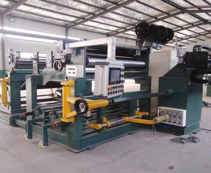
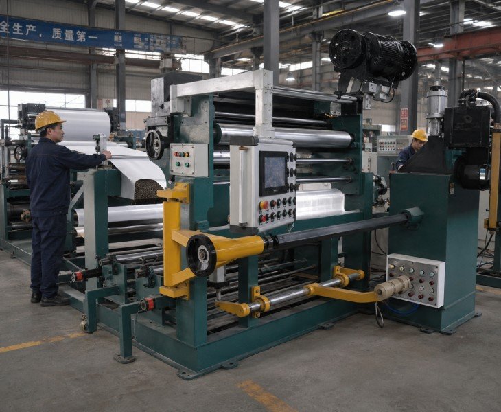
The winding process is precisely controlled by a CNC system, ensuring that each turn of foil is neatly arranged and the number of turns is accurate.

After setting the parameters, the winding process can be completed automatically, reducing errors caused by manual intervention.

Winding parameters can be adjusted through a visual touch interface, making it easy for operators to learn and use.
What Information Is Required for a Customized Foil Winding Machine?
| Information | Details to Provide | Used to Confirm |
|---|---|---|
| Foil Material | Copper or aluminum, width × thickness | Decoiler, tension and joining system |
| Coil Drawing | Coil size, shape and finished weight | Mandrel, torque and machine capacity |
| Insulation and Leads | Insulation specification and lead-bar design | Feeding and welding configuration |
| Production Requirement | Output, automation level and FAT criteria | Control functions and acceptance plan |
Send your foil specification, coil drawing and production requirements for machine configuration review.
How Should Transformer Foil Coil Quality Be Verified?
Finished foil-coil quality should be evaluated against the approved drawing and process specification rather than general claims such as high precision or stable quality.
Inspect the foil position, edge alignment, coil dimensions, number of turns, insulation position, layer overlap, conductor surface, wrinkles, telescoping, lead-bar position, joint quality and mandrel stability.
For repeated production, compare coils made at the beginning, middle and end of an agreed test run. Record the material batch, machine settings, measuring tools, acceptance limits and results in the FAT report.
Define the Automation Boundary Before Purchase
The word “automatic” should be divided into specific machine functions.
Confirm whether the proposed model automatically controls conductor decoiling, insulation feeding, foil tension, edge alignment, spindle speed, turn counting, pressure rollers, welding position, conductor cutting and program recall.
Operations that remain manual should also be listed, including reel loading, foil threading, mandrel installation, lead-bar positioning, welding preparation, insulation setup, coil removal and finished-part inspection.
Copper vs Aluminum Transformer Foil Winding Projects
| Comparison Item | Copper Foil | Aluminum Foil |
|---|---|---|
| Material | Confirm copper grade, temper and surface condition | Confirm aluminum alloy, temper and surface condition |
| Foil and Reel Data | Provide width × thickness, reel size and weight | Provide width × thickness, reel size and weight |
| Machine Configuration | Confirm tension, alignment and copper joining method | Confirm tension, alignment and aluminum joining method |
| FAT Test | Test a representative copper foil coil | Test a representative aluminum foil coil |
Copper and aluminum foil should be tested separately because their tension, handling and joining requirements may differ.
Critical Foil Winding Process Controls
Foil-coil quality depends on coordinated control of conductor tension, edge alignment, insulation feeding, conductor joining and mandrel support. Each system should be defined in the proposed configuration and verified using representative materials during FAT.

Foil tension should be selected according to the conductor material, width, thickness, reel condition, coil geometry and winding speed. The quotation should identify whether tension is controlled mechanically, pneumatically, electrically or through a closed-loop system.
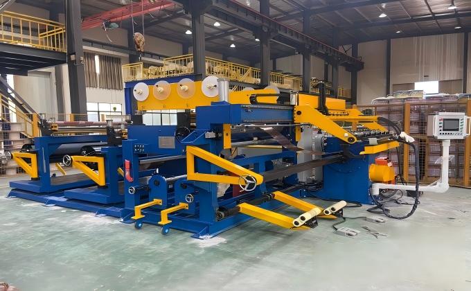
Edge alignment affects the finished coil profile and should be verified using the customer’s actual foil and insulation materials. Confirm the sensing, correction and adjustment method rather than relying only on the term “automatic alignment.”
Provide the conductor material, foil width and thickness, reel dimensions and weight, coil drawing, finished coil weight, insulation specification, layer structure, lead-bar design, joining method, production output and workshop utilities.
A machine may be configured for both materials, but compatibility depends on the approved foil ranges, reel handling, tension system, edge alignment, joining process and control settings. Both materials should be tested separately during FAT.
No. Automation may apply to only some functions, such as spindle control, turn counting, tension, edge alignment or insulation feeding. The quotation should state which processes are automatic and which remain manual.
Potential causes include inconsistent foil tension, poor incoming material condition, incorrect guide adjustment, unstable reel braking, misaligned mandrels, inappropriate winding speed or incorrect pressure-roller settings. The actual cause should be identified through material and process testing.
The joining process depends on the conductor material, foil dimensions, lead-bar design and customer specification. Confirm whether the proposed solution uses TIG welding, cold-pressure welding or another approved process.
Inspect the turn count, coil dimensions, edge profile, layer structure, insulation position, surface condition, lead position, joint quality and repeated-coil variation against the approved drawing and FAT criteria.
A wire winding machine processes round, rectangular or strip conductors through wire guiding and tensioning. A foil winding machine processes wide copper or aluminum foil and normally requires dedicated conductor decoiling, foil tension, edge alignment, insulation feeding and conductor joining.
Related Products
 Distribution Foil Winding Machine Transformer
 Copper Foil/Aluminum Foil Winding Machine Transformer
 Automated Foil Winding Machine Transformer
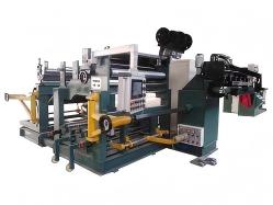 Power Foil Winding Machine Transformer

