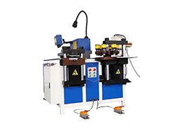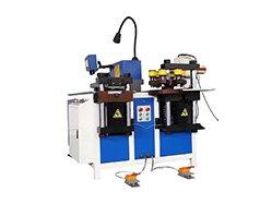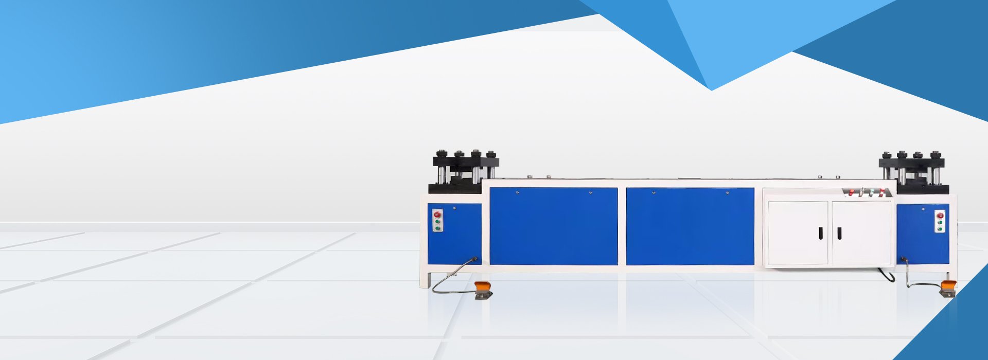
Your Double-Head Busbar Bending Machine Manufacturer
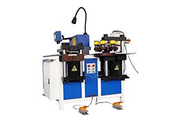
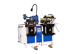
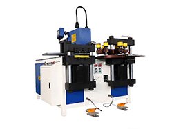
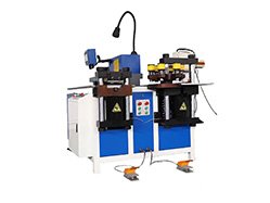
FengHua manufactures double-head busbar bending equipment for double-end forming applications. Compared with processing both ends separately on a single-head machine, a correctly configured double-head layout may reduce repeated workpiece turning and repositioning. The current source configuration is dedicated to busbar bending and is listed for a maximum processing thickness of 8 mm and a maximum processing width of 300 mm. Machine selection should be based on the material, width, thickness, raw length, bend positions, bend directions, required inside radii, finished angles and batch-output requirement. The quotation should also define the working sequence of the two bending heads, tooling, workpiece support and acceptance method.
Double-Head Busbar Bending Machine Configurations and Applications
FengHua configures the current double-head busbar bending platform for four common purchasing requirements. Final material capacity, tooling, head arrangement, control functions and model designation are recorded in the technical quotation.
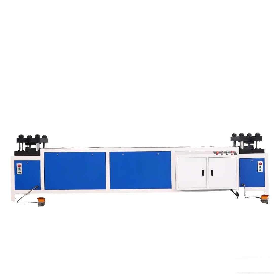
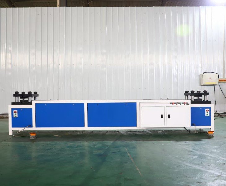
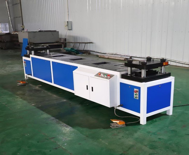
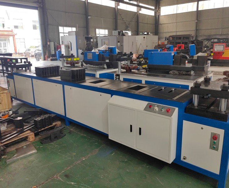
The current source configuration is listed for busbars up to 8 mm thick and 300 mm wide, with 500 kN listed bending force, a 5.5 kW motor, 380 V power supply and a 4,000 × 600 × 1,200 mm workbench.
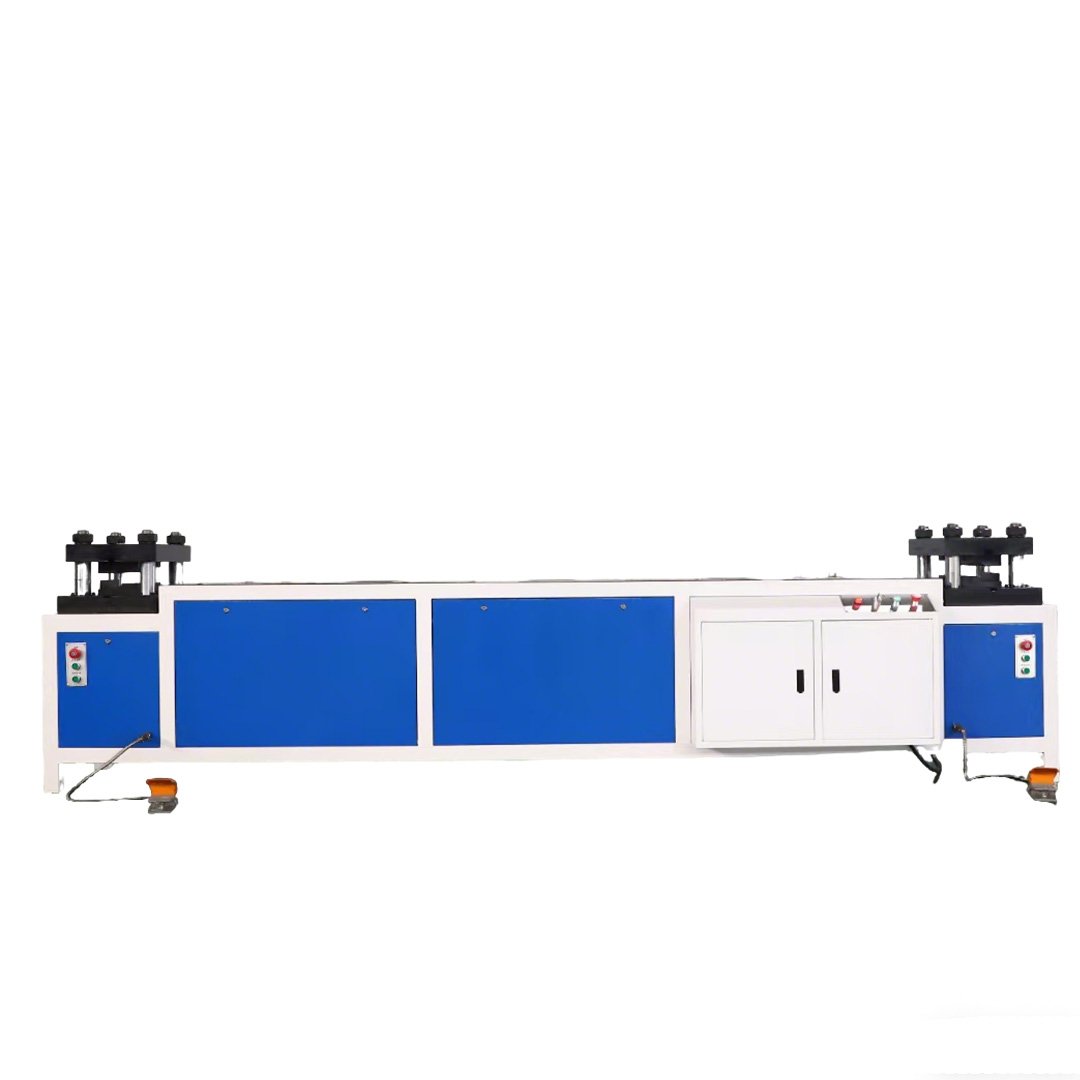
Copper and aluminum applications are evaluated separately according to material grade, temper, width, thickness, bend direction, inside radius, springback, and surface requirements. The same capacity and tooling settings should not be assumed for both materials.
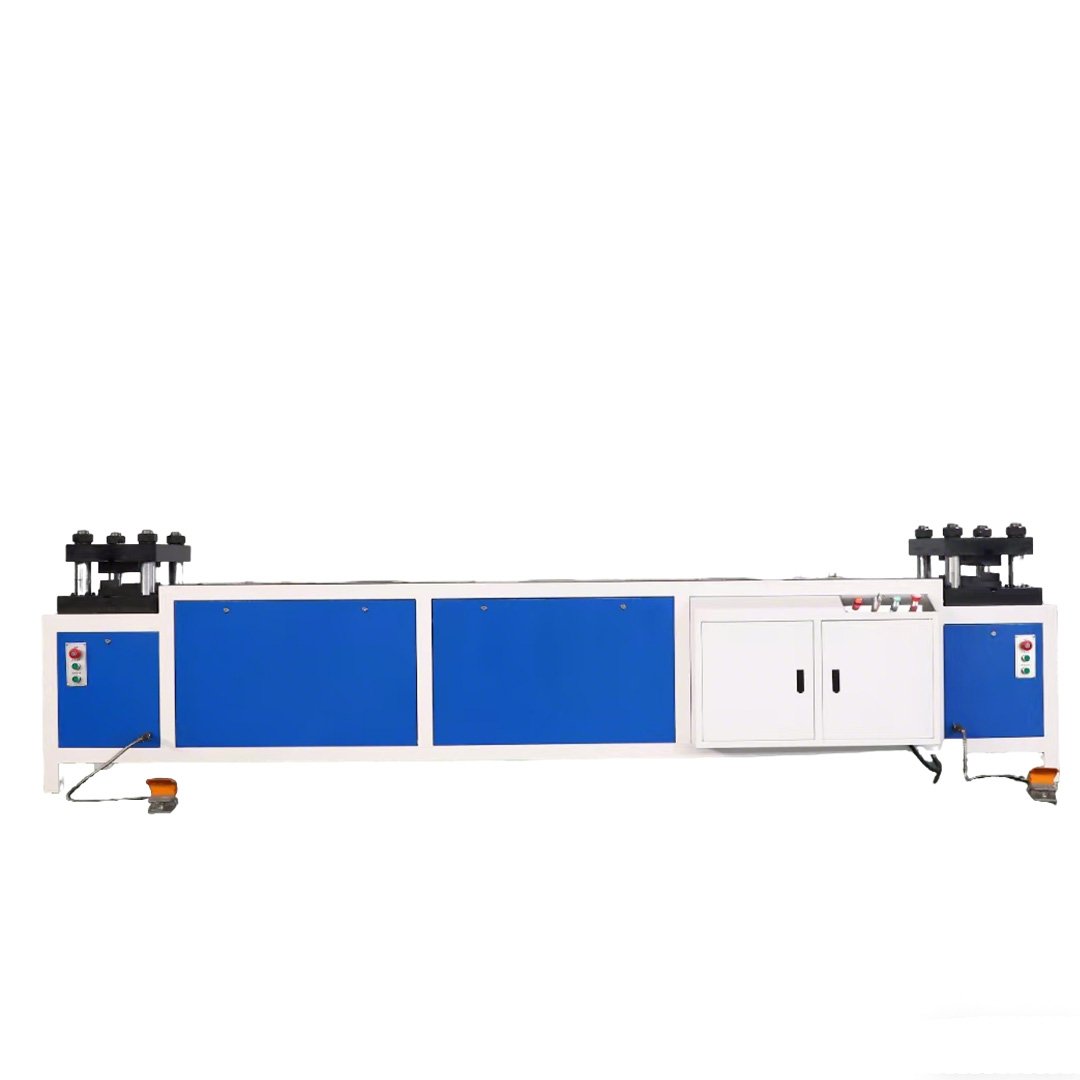
Configured for busduct or busway connector bars requiring forming operations at both ends. Head spacing, bend sequence, clamping, tooling and finished-part geometry must be reviewed using the actual connector drawing.
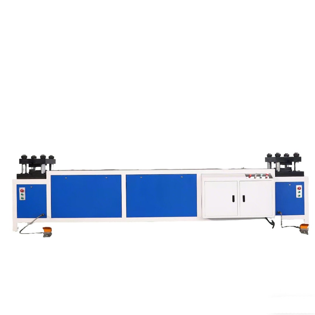
For special busbar lengths, bend positions, tooling, material supports or electrical requirements, FengHua reviews the application and records the approved machine scope in the technical quotation.
Verified Double-Head Busbar Bending Machine Specifications
| Parameter | Verified value | Parameter | Verified value |
|---|---|---|---|
| Machine type | Busbar Double-End Bending Machine | Main function | Busbar Press Bending |
| Maximum processing thickness* | 8 mm | Maximum processing width* | 300 mm |
| Bending force** | 500 kN | Motor power | 5.5 kW |
| Voltage*** | 380 V | Machine weight | 1,100 kg |
| Workbench dimensions**** | 4,000 × 600 × 1,200 mm | Place of origin | Jinan, Shandong, China |
The source sheet states general maximum processing dimensions but does not define the applicable material grade, temper, bend direction, inside radius or workpiece geometry. Final capacity must be confirmed against the actual drawing and material.
The source sheet lists 500 kN bending force but does not state whether this is the total machine force or the force of each bending head. This definition must be recorded in the technical quotation. 380 V represents the source configuration. Frequency, phase, destination voltage and electrical requirements must be confirmed before order. The source sheet identifies 4,000 × 600 × 1,200 mm as the workbench dimensions. It should not be presented as the overall machine dimensions until confirmed.
Key Features of the Double-Head Busbar Bending Configuration

The machine scope is reviewed according to material, width, thickness, raw length, bend positions, inside radii, finished angles, and output requirements.

The current source sheet lists 500 kN bending force. The quotation must clarify whether this value applies to one bending head or to the complete machine.

The double-head layout is intended for workpieces requiring bending operations at both ends. Actual handling reduction and complete cycle time should be verified using the approved workpiece.

The source configuration lists two oil pumps, two relief valves and two solenoid valves. Final model codes and quantities should match the approved bill of materials.
Drawing-Based Double-Head Busbar Bending Configuration
Different busbar projects may require different material grades, widths, thicknesses, raw lengths, bend positions, inside radii and
finished angles. Before confirming a custom configuration, FengHua should review theworkpiece drawing, material, bending sequence, tooling clearance,
workpiece support, head-spacing requirement, electrical supply and factory layout. The approved quotation should state the supported workpiece, included tooling, machine limitations, electrical configuration, test items and acceptance method.
How to Verify Repeatable Double-End Bending
Repeatable finished parts depend on more than hydraulic force. Material grade and temper, tooling, clamping, workpiece support, bend sequence, inside radius and inspection method can all affect the final result. Bending results should be measured after the workpiece is released from the tooling. Record the released angle, bend-line position, inside radius, end-to-end geometry and visible surface condition. For batch verification, compare the first, middle and final conforming
parts under the same material, tooling and setup conditions.
How to Evaluate Double-End Bending Cycle Time
Complete cycle time should include material loading, positioning, clamping, bending, unloading and inspection. A machine stroke or hydraulic speed value alone does not represent production output. When comparing a double-head configuration with a single-head workflow, test the same workpiece and record the total time required to produce one conforming part. Also record operator count, tooling changes and any repositioning steps.
How to Compare Double-Head Busbar Bending Machine Manufacturers in China
There is no universally recognized official “Top 10” ranking for double-head busbar bending machine manufacturers in China. Compare suppliers by verified machine specifications, actual double-end bent samples, head-spacing range, per-head or total force definition, tooling, released-angle measurements, FAT procedures, technical documentation and service availability in the destination country.
A company’s inclusion in a general busbar-machine manufacturer list does not prove that it manufactures this specialized machine. FengHua publishes a separate guide for comparing 10 general busbar machine manufacturers in China. It is a manufacturer-published comparison guide, not an official industry ranking or independent certification.
Processing Different Busbar Specifications
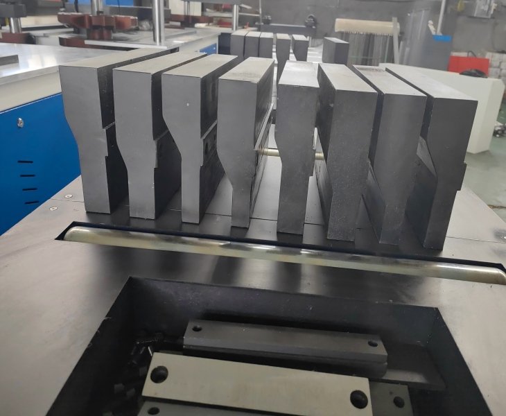
Different busbar specifications may require different tooling, bend settings, workpiece supports and head positions. Before changing products, operators should verify the material, drawing revision, tooling, setup, and first finished part. The machine should not be described as processing every specification without tooling changes or technical confirmation. Copper and aluminum applications should be reviewed separately. Material grade, temper and surface condition can affect bending springback, tooling pressure and visible marking.
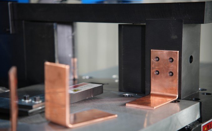
Fenghua CNC’s double-head busbar bending machine can easily process copper and aluminum busbars of different widths and thicknesses by adjusting the mold and bending stroke. There is no need to stop and change equipment; one machine can meet the various specifications required for your busbar processing projects, ensuring consistent bending quality for every busbar on your production line.
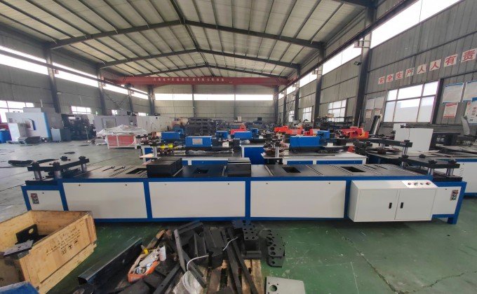
The current source sheet identifies hydraulic pump, relief valve, and solenoid-valve model codes together with Schneider contactors and thermal relays. The source sheet does not identify a PLC model, servo-controlled axis, HMI model, program-storage capacity, or automatic material-recognition function. These features should not be published unless they are confirmed in the final machine configuration.
The current source sheet lists a maximum processing thickness of 8 mm and a maximum processing width of 300 mm. Final capacity depends on material grade, temper, bend direction, inside radius and workpiece geometry.
The source sheet lists 500 kN bending force. The technical quotation should state whether this represents the force of one bending head or the total machine force.
The current source sheet does not define the working sequence. The quotation should state whether the heads work simultaneously, independently, or in a controlled sequence.
Copper and aluminum applications can be evaluated, but the same capacity and tooling settings should not be assumed. Material grade, temper, dimensions, springback, and surface requirements must be confirmed separately.
The current source sheet identifies Schneider contactors and thermal relays but does not identify a PLC model, servo axis, HMI, positioning system, or program-storage function. Required control functions should be confirmed before quotation.
Send the workpiece drawing, material grade and temper, width, thickness, raw length, bend positions, bend directions, inside radii, required finished angles, batch quantity, output target, and destination voltage.