
Quick Answer
A power transformer winding machine rotates an approved mandrel to form copper or aluminum conductors into transformer coils.
The required configuration depends on the finished winding load, coil dimensions, conductor specification, spindle speed, torque, winding direction, turn count, mandrel support, tension method and guiding process.
Automatic wire traversing, closed-loop tension control, touchscreen operation and program storage are separate configuration items. They should not be assumed to be included unless they are listed in the approved technical quotation.
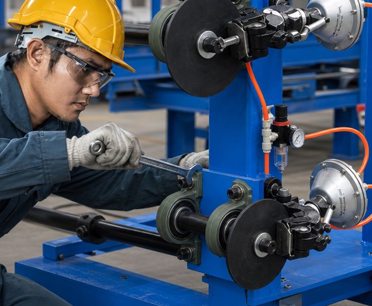
What Is a Power Transformer Winding Machine?
A power transformer winding machine supports the mechanical winding of copper or aluminum conductors onto an approved mandrel for producing transformer coils.
The machine normally provides spindle rotation, torque, mandrel support and turn counting. Depending on the proposed configuration, it may also include reversible winding, speed control, conductor guiding, tension control or automatic wire traversing.
The machine does not independently determine the transformer’s electrical design. The conductor, turn count, coil dimensions, insulation structure, cooling ducts, leads and tap positions must be defined in the approved coil drawing and winding-process specification.
The final equipment configuration should be confirmed against the winding load, mandrel drawing, conductor specification, workshop layout and FAT requirements.
Power Transformer Winding Machine Configurations
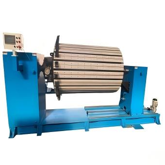
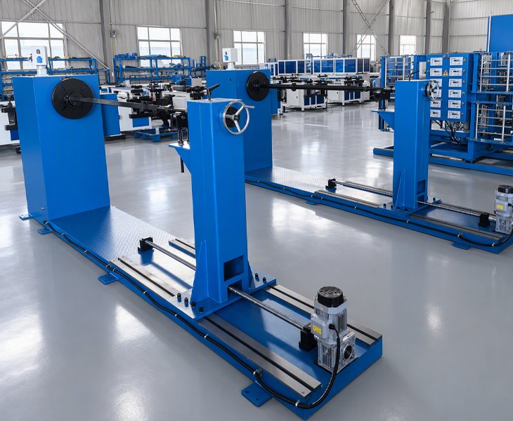
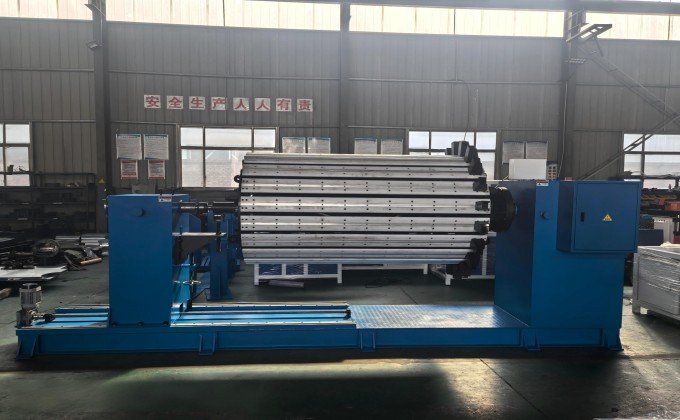
Designed for larger transformer coils requiring horizontal mandrel and tailstock support. Confirm the finished winding load, spindle torque, shaft length, mandrel interface and braking requirements.
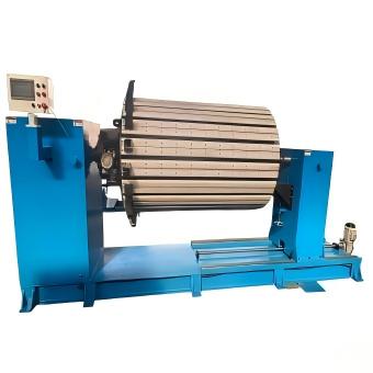
Suitable for multi-layer high-voltage wire coils requiring controlled conductor placement, interlayer insulation and defined lead or tap positions.
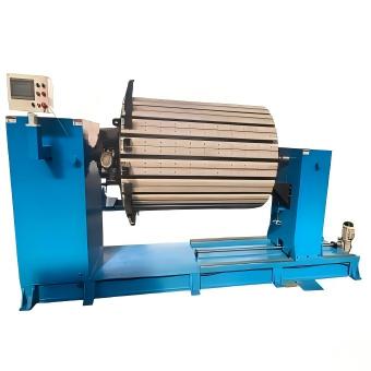
Used for low-voltage coils made from round wire, rectangular wire or approved strip conductors. Confirm the conductor format, torque, guiding method and coil dimensions.
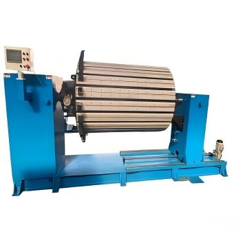
Suitable for repeated coil specifications where selected winding, traversing or program functions require automatic control. Confirm every controlled axis and manual operation.
How to Select a Power Transformer Winding Machine
| Production Requirement | Starting Configuration | What to Confirm |
|---|---|---|
| Larger coils requiring horizontal support | Horizontal Winding Machine | Load, torque, shaft, mandrel and brake |
| Multi-layer high-voltage wire coils | HV Winding Machine | Guiding, tension, insulation, leads and taps |
| Low-voltage wire or strip coils | LV Winding Machine | Conductor format, coil size and mandrel |
| Repeated standardized coils | Automatic Winding Configuration | Controlled axes, program functions and cycle time |
The machine with the highest speed or largest frame is not automatically the correct choice. Suitability depends on the dynamic winding load, required torque, mandrel support, conductor process and finished-coil acceptance criteria.
Functions to Confirm Before Selecting a Power Transformer Winding Machine

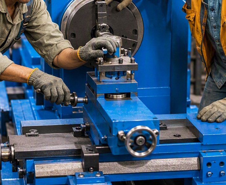
Confirm the maximum operating load, load distribution, shaft dimensions, effective winding length, mandrel interface, tailstock movement, locking method and finished-coil removal procedure.

Confirm the available speed range, maximum torque, transmission method, operating speed under load, stopping performance and motor-braking function.

Confirm the counter range, forward and reverse counting, power-off memory, winding-direction control and FAT verification method.

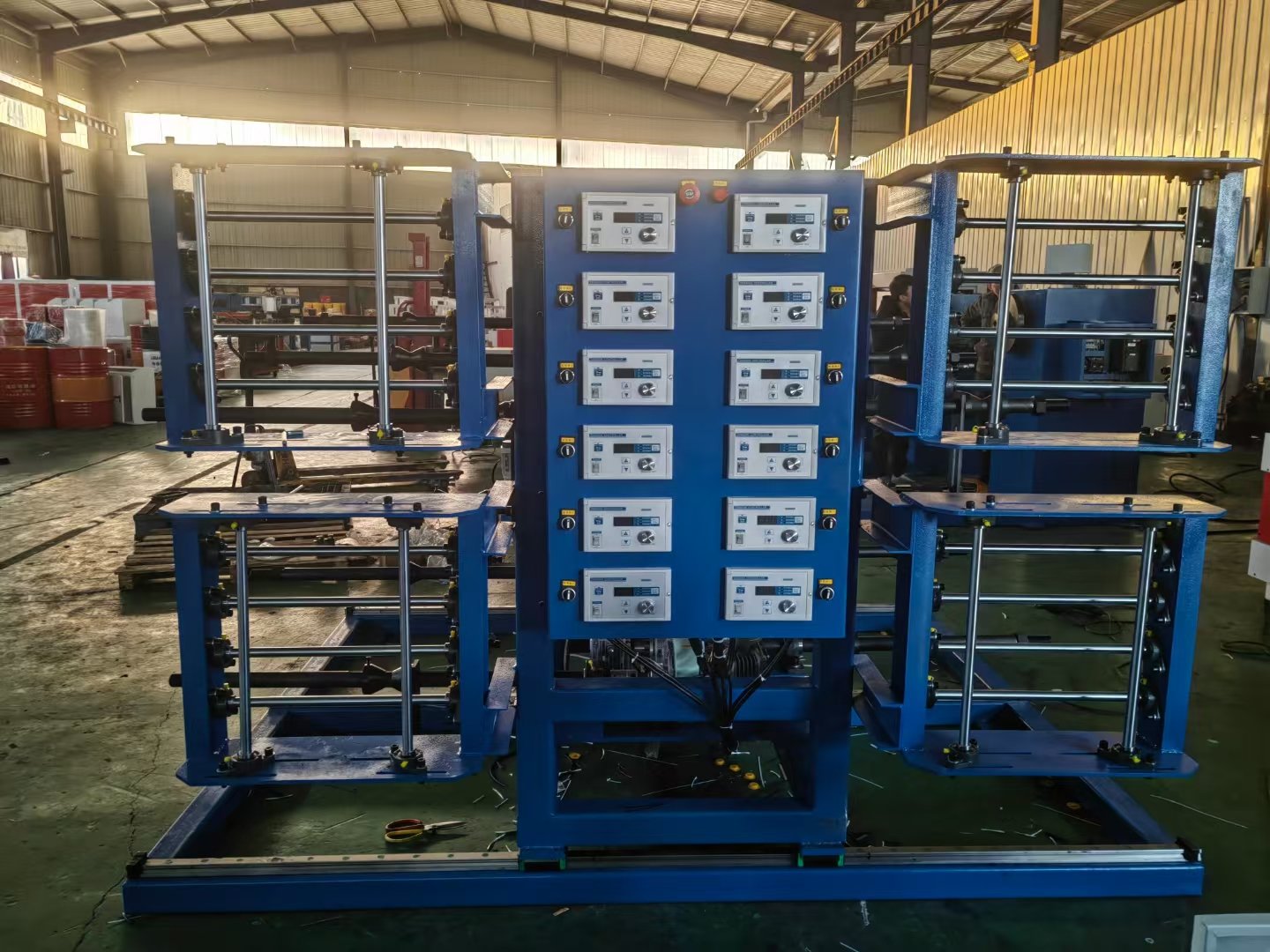
Confirm the tension principle, conductor-guiding method, insulation process, lead positioning and which operations are automatic, assisted or manual.
How Should Conductor Tension Be Confirmed?
Tension performance should be defined according to the proposed tension system rather than described only as stable or uniform.
Confirm the tension-control principle, adjustment method and operating procedure against the conductor material, cross-section, insulation, reel condition, winding speed, coil diameter and layer structure.
During FAT, use representative conductor and reel conditions. Record the tension settings, operating speed, conductor condition, layer arrangement and finished-coil results.
Do not state a universal tension range or tension accuracy until the exact components, measuring method and acceptance criteria are confirmed.
How Should Coil Layer Arrangement Be Verified?
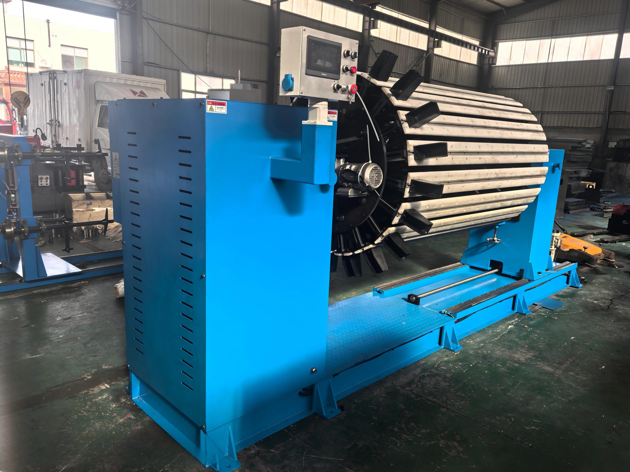
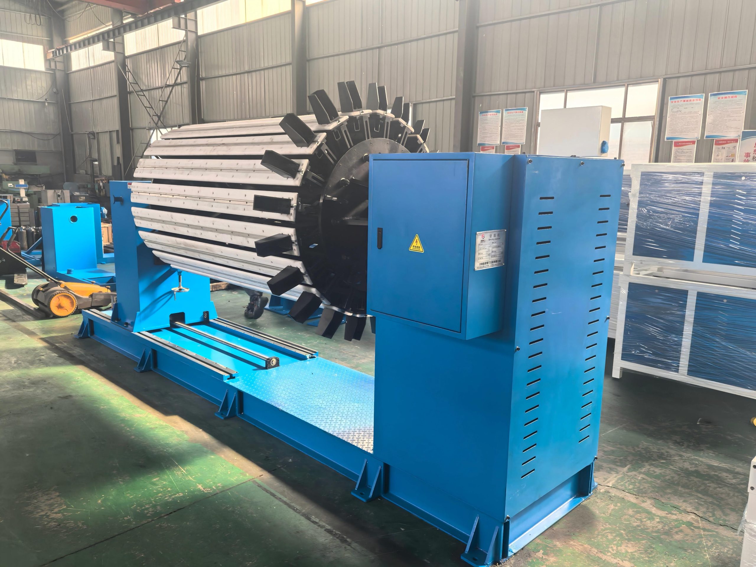
Layer arrangement should be checked against the approved coil drawing and winding-process specification rather than judged only by visual neatness.
Inspect the conductor position, layer count, coil internal and external dimensions, finished height, insulation position, cooling-duct arrangement, start and end leads, tap positions and surface condition.
For repeated production, compare sample coils produced at the beginning, middle and end of the agreed test run. Record the measuring instruments, tolerance limits and actual results in the FAT report.
Sample winding verifies the machine configuration and winding process. Electrical testing of the completed coil or transformer remains a separate quality-control stage.
What Information Is Required Before Quotation?
Before machine selection, provide the transformer application, conductor material and cross-section, coil dimensions, finished winding load, number of turns, winding direction, layer and insulation structure, lead or tap positions, mandrel drawing, required output, automation level, workshop voltage and FAT criteria. These details are used to confirm the spindle, torque, shaft, mandrel support, tension, guiding, control functions and acceptance plan.
How Should Power Transformer Coil Quality Be Verified?
| Inspection Area | What to Confirm |
|---|---|
| Winding Data | Turn count, winding direction and layer quantity |
| Coil Dimensions | Inner size, outer size, axial height and finished shape |
| Process Structure | Conductor arrangement, insulation and cooling ducts |
| Lead Arrangement | Start lead, end lead and tap positions |
| Surface and Support | Conductor damage, insulation damage and mandrel stability |
The acceptance plan should define the drawing datum, measuring instruments, sample quantity, tolerance limits and recording method before sample winding begins.
How to Compare China’s Top 10 Transformer Winding Machine Manufacturers
A top-10 manufacturer list should be used as an initial supplier shortlist rather than proof that a proposed machine is suitable for your transformer coil.
For a power transformer winding project, compare the actual machine configuration, winding-load evidence, spindle system, mandrel interface, conductor process, sample coil and FAT results.
| Comparison Factor | What to Confirm | Evidence to Request |
|---|---|---|
| Machine Match | Coil type, conductor, load and mandrel | Signed specification and layout |
| Spindle System | Speed, torque, shaft, support and brake | Drawings and load-test record |
| Process Functions | Counting, direction, tension, guiding and automation | Function list and demonstration |
| FAT and Service | Sample coil, acceptance, documents, warranty and parts | Signed FAT and service scope |
Published manufacturer lists should not replace technical verification. Final supplier selection should be based on the approved configuration, representative winding test, FAT evidence and contract terms.
Define the Automation Boundary and Complete Winding Cycle Automation Boundary
The term automatic should be divided into specific functions. Confirm whether the proposed configuration controls spindle speed, turn counting, winding direction, wire traversing, tension, stopping, program storage or alarm functions.
Material loading, conductor threading, mandrel installation, insulation placement, cooling-duct insertion, lead positioning, coil removal and final inspection may remain manual.
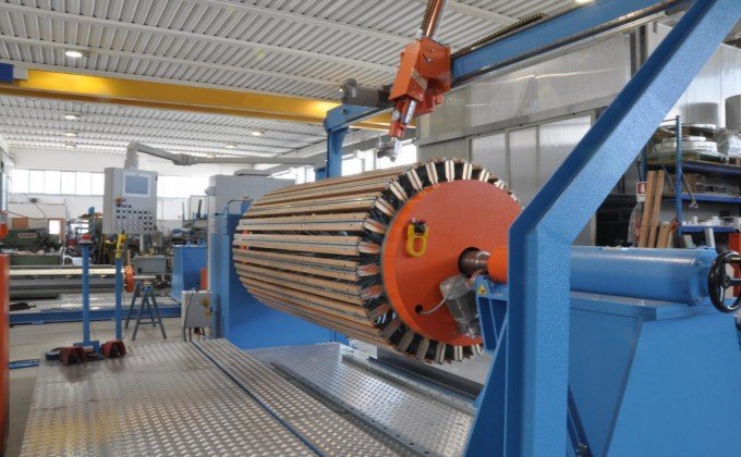
Do not compare equipment only by maximum spindle speed. Complete cycle time should include mandrel installation, conductor preparation, initial alignment, parameter setting, winding, process interruptions, insulation placement, lead handling, coil removal and finished-coil inspection.
For supplier comparison, use the same conductor, mandrel and coil drawing. Record setup time, operating time, manual interventions, conforming coils and rework.
A power transformer winding machine rotates an approved mandrel to form copper or aluminum conductors into transformer coils according to the specified winding process.
It depends on the conductor, coil dimensions, winding load, mandrel, torque, tension and guiding requirements. HV and LV coils may require different machine configurations and process equipment.
Compatibility must be confirmed according to the conductor material, shape, cross-section, insulation, reel condition, tension method, torque demand and coil geometry.
No. Automation may apply only to selected functions such as speed control, turn counting, wire traversing, tension control or program storage. Manual and automatic operations should be listed separately.
Confirm the operating load, load distribution, mandrel weight, shaft support, operating speed and FAT test method. Static frame capacity alone does not prove the allowable dynamic winding load.
No. Operating speed depends on the winding load, conductor, mandrel balance, torque demand, insulation process and finished-coil quality requirements.
Produce an agreed sample batch using the same conductor, mandrel and settings. Compare turn count, dimensions, layer arrangement, insulation, leads and surface condition using recorded measurements.
Provide the conductor specification, coil drawing, winding load, turns, direction, layer structure, insulation, mandrel drawing, production output, automation requirement, voltage and FAT criteria.
Use the approved conductor, mandrel and coil requirements to verify rotation, load, braking, counting, tension, guiding, finished dimensions, safety, documents and spare parts.

