

Quick Answer
An HV winding machine forms insulated round or rectangular conductors into multi-layer high-voltage transformer coils according to an approved winding drawing.
The machine provides spindle rotation, torque, turn counting and mandrel support. Depending on the configuration, it may also include conductor guiding, variable-frequency speed control, reversible winding, program storage or tension-control functions.
Automatic wire traversing, closed-loop tension control, touchscreen operation and real-time dimensional monitoring should be confirmed separately and should not be assumed to be included with every HV winding machine.
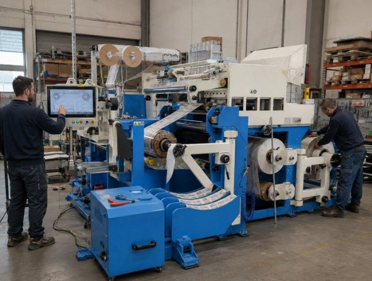
What Is an HV Transformer Winding Machine?
An HV transformer winding machine winds insulated wire conductors onto an approved mandrel to produce a high-voltage transformer coil.
HV coils commonly require controlled conductor placement, layer-by-layer winding, interlayer insulation, defined lead or tap positions and accurate turn-count records.
The winding machine supports the mechanical winding process, but it does not determine the transformer’s electrical design or independently guarantee the finished transformer’s electrical performance. The conductor, turns, insulation, dimensions and lead arrangement must be defined in the approved coil drawing and winding-process specification.
HV Transformer Winding Machine Configurations
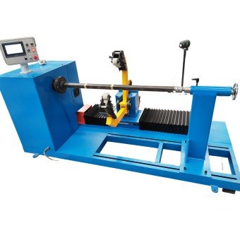
Designed for multi-layer HV wire coils requiring horizontal mandrel and tailstock support. Confirm the winding load, spindle torque, effective shaft length, coil dimensions and mandrel interface.
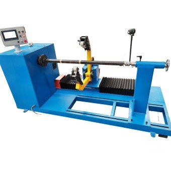
Suitable for coils requiring clockwise or counterclockwise winding. Confirm the winding direction, turn-counting method, braking function and power-off memory.
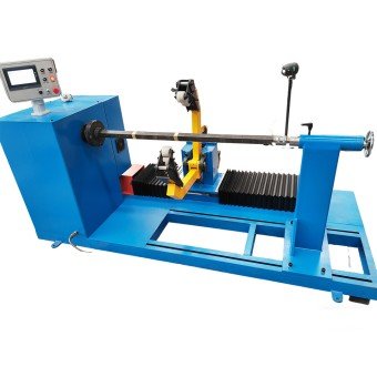
Configured according to the conductor, coil dimensions, layer structure, mandrel, winding load, tension method, guiding system and required control functions.
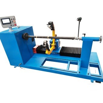
Configured according to the conductor, coil dimensions, layer structure, mandrel, winding load, tension method, guiding system and required control functions.
How to Select the Right HV Winding Machine
| Requirement | Starting Configuration | What to Confirm |
|---|---|---|
| Larger horizontal HV coils | Horizontal HV Winding Machine | Load, torque, shaft and mandrel |
| Defined winding direction | Reversible HV Winding Machine | Rotation, counter, brake and memory |
| Multi-layer insulated coils | Multi-Layer Winding Configuration | Guiding, tension, insulation and leads |
| Different coil specifications | Custom HV Winding Machine | Conductor range, changeover and FAT |
Terms such as CNC, automatic or servo do not confirm the complete machine configuration. Every controlled and manual function should be listed separately in the technical quotation.
Functions to Confirm Before Selecting an HV Winding Machine

Confirm whether the proposed machine uses manual guiding, mechanical guiding, servo traversing or another approved method. The guiding system must match the conductor shape, cross-section, layer arrangement and coil width.

Confirm the tension-control principle, adjustable range and operating procedure according to the conductor material, insulation, reel condition, winding speed and coil structure.

Confirm the counter range, forward and reverse counting, power-off memory, winding-direction control and FAT verification method.

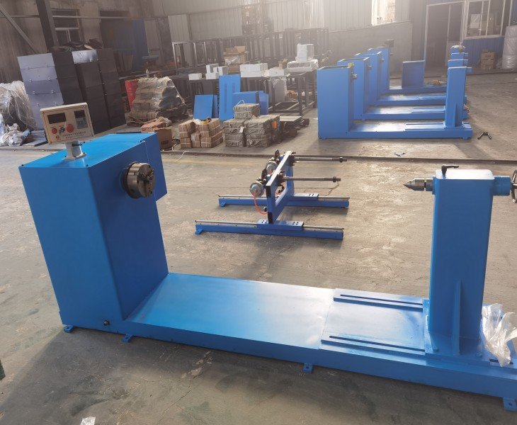
Confirm the winding load, shaft dimensions, effective spindle length, mandrel interface, tailstock structure, locking method and finished-coil removal procedure.
How Should HV Coil Winding Quality Be Verified?
Finished HV coil quality should be evaluated against the approved drawing and winding-process specification rather than general claims such as high precision or perfect layer arrangement.
Inspect the final turn count, winding direction, internal and external dimensions, axial height, layer arrangement, conductor spacing, insulation position, cooling ducts, lead and tap positions, surface condition and mandrel stability.
For repeated production, compare coils produced at the beginning, middle and end of the agreed test run. Record the conductor, insulation materials, settings, measuring instruments, acceptance limits and actual results.
Sample winding verifies the machine configuration and winding process. Electrical testing of the completed coil or transformer remains a separate quality-control stage.
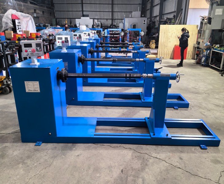
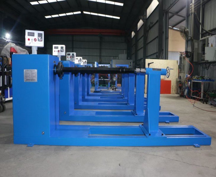
Managing Different HV Coil Specifications
Producing several HV coil designs may require changes to the mandrel, conductor guide, shaft position, tension settings, insulation setup and operating parameters.
The technical quotation should identify the supported conductor range, required tooling and changeover procedure. For mixed-specification production, include a practical changeover and sample-winding test during FAT to verify the adjustment steps, setup time and finished-coil results.
Define the Automation Boundary Before Purchase
The term “automatic” should be divided into specific machine functions.
Confirm whether the proposed configuration automatically controls spindle speed, turn counting, conductor traversing, tension, winding direction, stopping, program recall or alarm functions.
Also identify the manual operations, including conductor loading, threading, mandrel installation, insulation placement, cooling-duct insertion, lead and tap positioning, coil removal and finished-coil inspection.
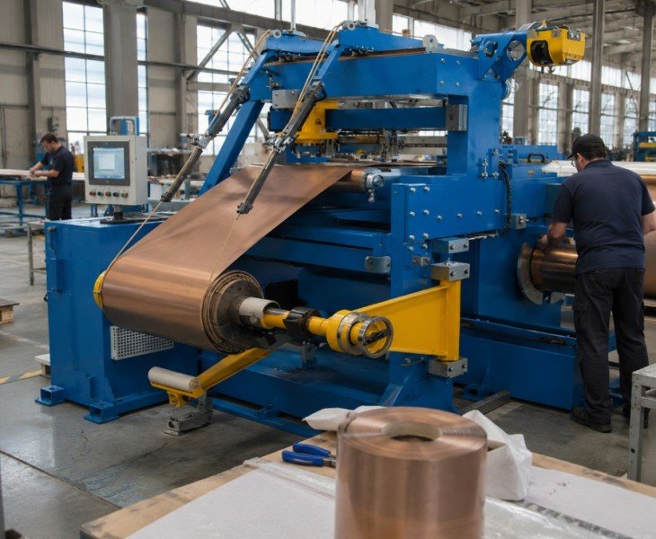
HV Winding Machine FAT Checklist
| FAT Check | What to Verify | Evidence |
|---|---|---|
| Configuration and Safety | Machine matches the quotation and contracted protection operates | Configuration sheet and checklist |
| Rotation, Counter and Brake | Direction, known turns, memory and stopping performance | Test report and video |
| Conductor, Tension and Guiding | Representative conductor runs under approved settings | Settings and sample |
| Mandrel, Insulation and Sample Coil | Stable support, layer arrangement, insulation, leads and dimensions | Inspection report and photos |
| Documents and Spare Parts | Manuals, drawings, component list and contracted parts | Document index and packing list |
Agree the conductor, insulation, mandrel, test load, sample quantity, measuring instruments and acceptance limits before FAT.
How to Compare China’s Top 10 Transformer Winding Machine Manufacturers
There is no universally recognized official ranking of China’s top 10 transformer winding machine manufacturers. Published lists should be used only to create an initial supplier shortlist.
For an HV winding project, compare the actual configuration proposed for your conductor, coil drawing, insulation structure and mandrel rather than relying only on company size, model names or promotional rankings.
| Comparison Factor | What to Confirm | Evidence to Request |
|---|---|---|
| HV Coil Capability | Conductor, layers, insulation and coil capacity | Signed specification and sample coils |
| Process Functions | Guiding, tension, counting, rotation and stopping | Function list and live demonstration |
| Sample and FAT | Representative conductor, insulation and coil drawing | Sample coil and inspection report |
| Service Scope | Installation, training, warranty, documents and parts | Written service scope |
A top-10 manufacturer list is only a sourcing reference. Final selection should be based on the approved machine configuration, representative sample coil, FAT results and contract terms.
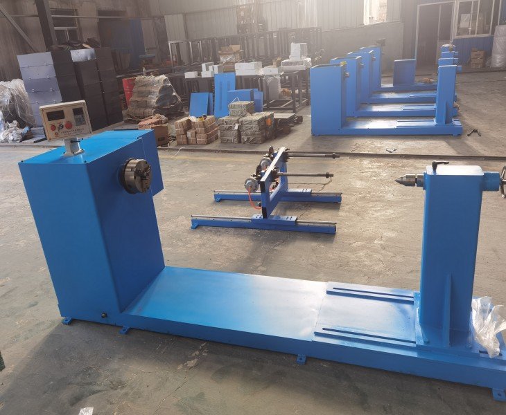
Efficient Continuous Production and Simplified Operation
Efficient continuous winding operation helps you improve the yield rate and production efficiency of your production line.
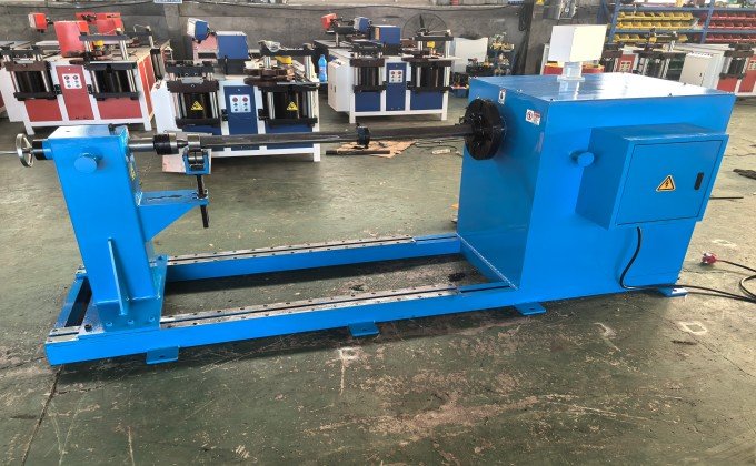
The HV Winding Machine is equipped with an intelligent control system that provides automatic control over the transmission system and tension control, enabling long-term continuous winding with high precision and stability. It shuts down, reducing the ideal for large-volume, high-demand transformer projects.
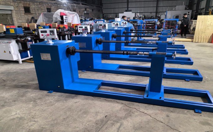
HV Winding Machine features a visual winding parameter that can be pre-entered into the system and directly recalled during the winding process. This manual experience allows your production line of winding parameters to be standardized.
An HV winding machine produces multi-layer high-voltage transformer coils from approved round or rectangular insulated conductors.
The term HV does not define one universal machine voltage range. Machine selection is based primarily on the physical conductor, coil dimensions, number of layers, winding load, mandrel and required winding process. The transformer’s voltage design is confirmed separately by the responsible electrical engineer.
Compatibility depends on the conductor material, shape, cross-section, insulation, reel arrangement, tension method, guiding system, torque and coil geometry. Provide the actual conductor specification before configuration confirmation.
FengHua provides installation and commissioning guidance, practical operation training, 24-hour technical support, and sufficient spare parts inventory.
No. Automation may apply only to selected functions, such as spindle speed, turn counting, conductor traversing or program recall. Automatic and manual operations should be listed separately in the quotation.
The method depends on the coil design and proposed machine configuration. Confirm whether insulation and ducts are positioned manually, with assisted feeding or through another agreed system, and verify the process during sample winding.
Confirm the tension principle, adjustable range and operating procedure according to the conductor, insulation, reel condition, winding speed and coil structure. The selected settings should be demonstrated with representative material during FAT.
Provide the conductor specification, coil drawing, turns, layers, winding direction, insulation arrangement, lead and tap positions, mandrel, winding load, output, voltage and FAT requirements.
Use approved conductor, insulation, mandrel and coil drawings to verify rotation, counting, braking, tension, guiding, insulation placement, finished dimensions, lead positions, safety and documentation.

