
Quick Answer
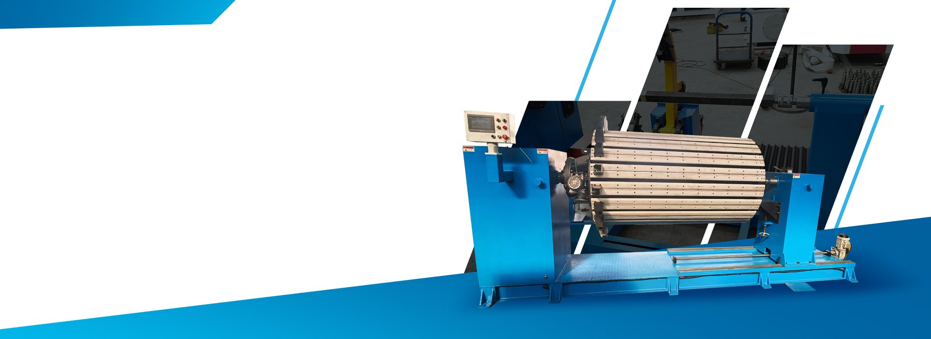
A round transformer winding machine rotates an approved mandrel to form copper or aluminum conductors into cylindrical transformer coils.
The required configuration depends on the conductor specification, coil dimensions, finished winding load, mandrel design, spindle speed, torque, winding direction, turn count, tension method and guiding system.
Automatic wire traversing, closed-loop tension control, touchscreen operation, program storage and fault monitoring are separate configuration items. They should not be assumed to be included unless they are listed in the approved technical quotation.
The term “round” describes the finished coil geometry. It should not be used as a synonym for toroidal winding unless the proposed machine uses a dedicated toroidal winding process.
What Is a Round Transformer Winding Machine?
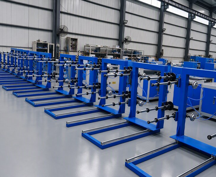
A round transformer winding machine supports the mechanical winding of conductors onto an approved cylindrical mandrel to produce round transformer coils.
The machine normally provides spindle rotation, torque, mandrel support and turn counting. Depending on the proposed configuration, it may also include reversible winding, variable-speed control, conductor guiding, tension adjustment or automatic wire traversing.
The winding machine does not independently determine the electrical design of the transformer. The conductor, turn count, coil dimensions, layer structure, insulation, cooling ducts, leads and tap positions must be defined in the approved coil drawing and winding-process specification.
Every controlled function, manual operation and unsupported requirement should be identified in the technical quotation before production begins.
Round Transformer Winding Machine Configurations
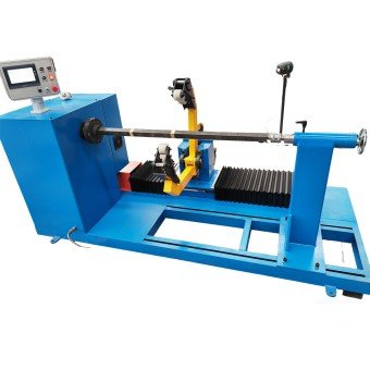
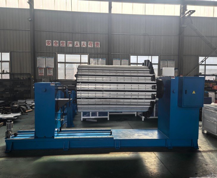
Designed for cylindrical transformer coils requiring horizontal mandrel and tailstock support. Confirm the winding load, spindle torque, effective shaft length, coil dimensions and mandrel interface.
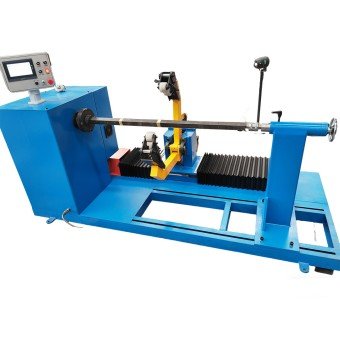
Suitable for coil processes requiring clockwise or counterclockwise winding. Confirm the winding direction, turn-counting method, braking function and power-off memory.
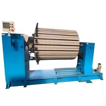
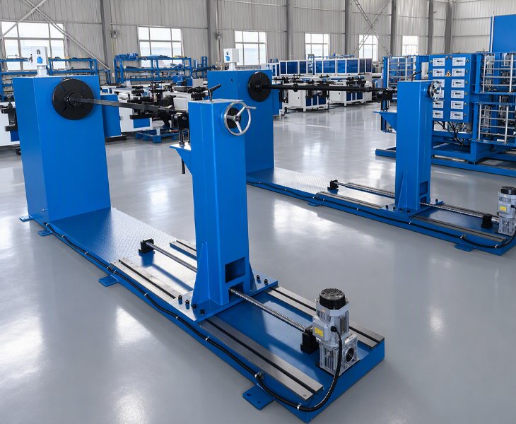
Reviewed for projects requiring controlled conductor placement across the winding width. Confirm whether guiding is manual, mechanical, servo-controlled or completed through another approved method.
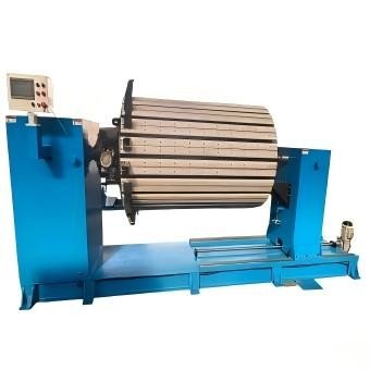
Configured according to the conductor, coil geometry, winding load, mandrel, tension method, guiding system, workshop layout and required control functions.
How to Select a Round Transformer Winding Machine
| Production Requirement | Starting Configuration | What to Confirm |
|---|---|---|
| Large cylindrical coils | Horizontal winding machine | Load, torque, shaft, tailstock and mandrel |
| Forward and reverse winding | Reversible winding machine | Direction, counter, braking and memory |
| Controlled conductor placement | Guided winding machine | Guide type, travel, pitch and tension |
| Frequent specification changes | Custom winding machine | Supported range, changeover and FAT |
The machine with the highest spindle speed is not automatically the best choice. Suitability depends on the winding load, required torque, mandrel support, conductor process and finished-coil acceptance criteria.
Functions to Confirm Before Selecting a Round Winding Machine

Confirm the maximum operating load, load distribution, shaft dimensions, effective winding length, mandrel interface, tailstock movement, locking method and finished-coil removal procedure.

Confirm the available speed range, torque, transmission method, operating speed under load, acceleration and deceleration settings, stopping performance and motor-braking function.

Confirm the counter range, forward and reverse counting, power-off memory, winding-direction control and FAT verification method.

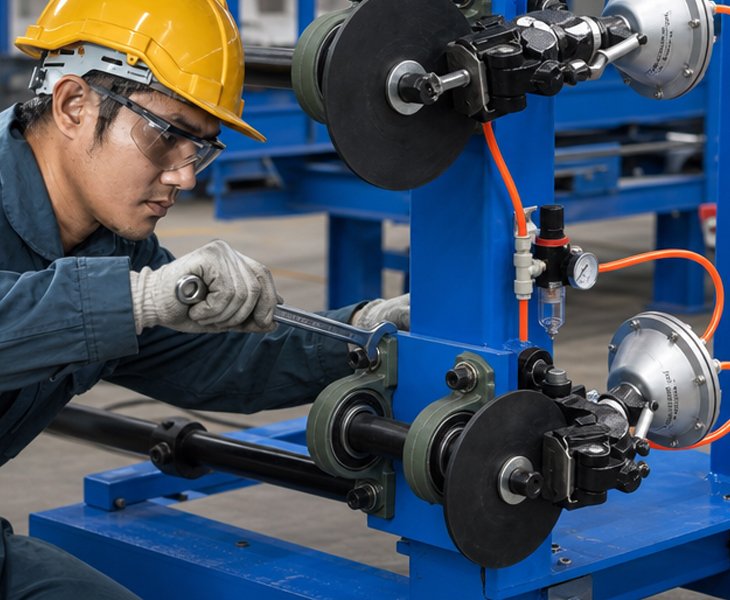
Confirm the conductor-tension principle, guiding method, adjustment procedure and whether each supplied function is manual, assisted or automatically controlled.
How Should Winding Speed Be Evaluated?
Maximum spindle speed should not be treated as the normal production speed for every coil.
Operating speed depends on the winding load, mandrel balance, conductor specification, torque requirement, tension method, guiding process, insulation operations and finished-coil quality requirements.
During FAT, verify acceleration, operating speed, deceleration and stopping with the approved mandrel and representative conductor. Record any conductor movement, layer displacement, tension variation or manual intervention.
Complete cycle time should include mandrel installation, conductor preparation, initial alignment, winding, required process interruptions, coil removal and finished-coil inspection.
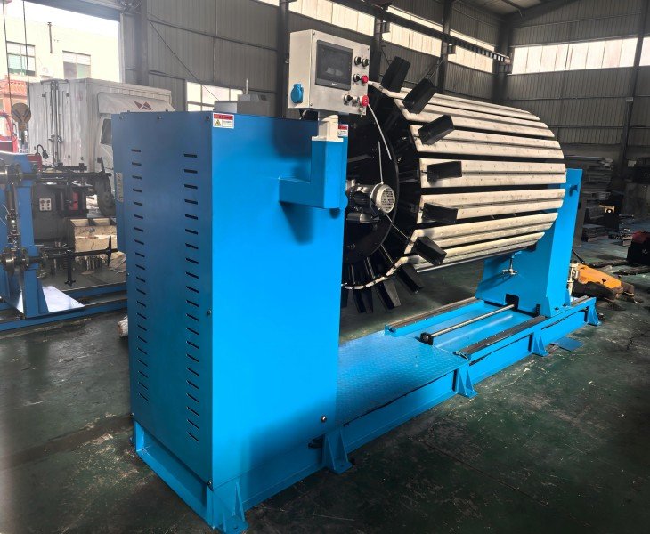
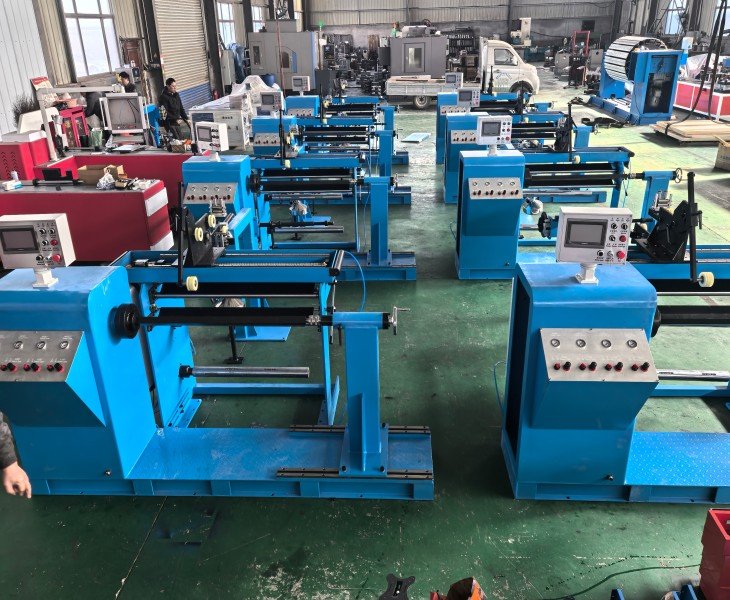
How Should Conductor Guiding Be Verified?
Conductor guiding should be verified through the supplied guide structure and the finished sample coil rather than through controller settings alone.
Confirm whether the conductor is positioned manually, through a mechanical guide or by a programmable traverse axis. Where a controlled traverse is included, record its effective travel, pitch range, direction reversal, edge correction, synchronization method and supported conductor dimensions.
During sample winding, inspect conductor spacing, crossed turns, layer transitions, axial position, coil height, lead positions and any conductor or insulation damage.
Automatic traversing can support repeated conductor placement, but it does not independently guarantee finished-coil conformity. The result also depends on the conductor, tension, mandrel, guide setup, winding speed and first-layer alignment.
Managing Different Round Coil Specifications
Switching between round coil designs may require changes to the mandrel, shaft position, conductor guide, pay-off arrangement, tension settings and operating parameters.
The technical quotation should identify the supported conductor and coil range, required tooling, changeover procedure and expected setup method.
For mixed-specification production, include a practical changeover and sample-winding test during FAT to verify the adjustment steps, setup time and finished-coil results.
How Should Round Coil Geometry Be Confirmed?
Round coil configuration should be based on the finished coil drawing rather than coil diameter alone.
Confirm the internal diameter, external diameter, axial height, winding length, layer quantity, conductor arrangement, insulation structure, lead positions, finished winding load and permitted dimensional tolerances.
The mandrel design should also account for the coil shape, shaft interface, locking method, support points, expected deformation and finished-coil removal procedure.
| Geometry Check | What to Confirm |
|---|---|
| Inner Diameter | Mandrel size, insulation and removal allowance |
| Outer Diameter | Finished winding build and layer quantity |
| Axial Height | Conductor placement and guiding range |
| Coil Shape | Roundness, deformation and support method |
| Lead Positions | Start, end and tap locations |
Agree the drawing datum, measuring instruments and acceptance limits before sample winding.
How to Compare China’s Top 10 Transformer Winding Machine Manufacturers
There is no universally recognized official ranking of China’s top 10 transformer winding machine manufacturers. Published lists should be used only to create an initial supplier shortlist.
For a round-coil winding project, compare the actual machine proposed for your conductor, coil geometry, winding load and mandrel rather than relying only on company size, maximum speed or promotional rankings.
| Comparison Factor | What to Confirm | Evidence to Request |
|---|---|---|
| Round-Coil Capability | Coil geometry, conductor and winding load | Signed specification and drawings |
| Spindle and Mandrel | Speed, torque, shaft, support and brake | Technical drawing and load test |
| Winding Functions | Counting, direction, tension and guiding | Function list and demonstration |
| FAT and Service | Sample coil, acceptance, warranty and parts | Signed FAT and service scope |
Define the Automation Boundary Before Purchase
The term “automatic” should be divided into specific machine functions.
Confirm whether the proposed configuration controls spindle speed, turn counting, winding direction, conductor traversing, tension, stopping, program storage or alarm functions.
Also identify the manual operations, including conductor-reel loading, threading, mandrel installation, initial conductor fixing, insulation placement, lead positioning, coil removal and finished-coil inspection.
A touchscreen or CNC controller does not prove that every material-handling and winding operation is automatic.
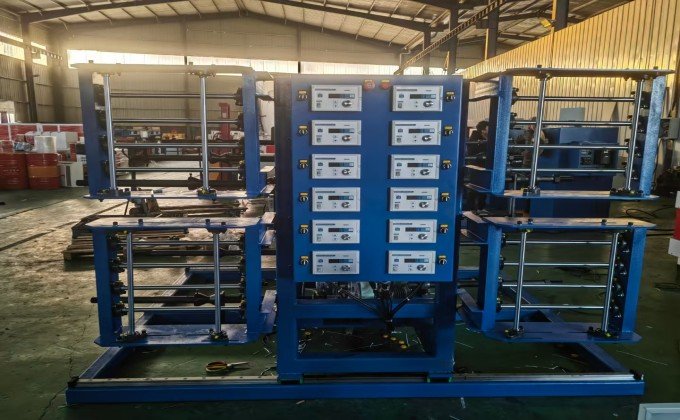
FengHua CNC’s circular winding machines are equipped with a real-time monitoring system that monitors the operation of the spindle, tension system, and wire arrangement structure. The system automatically alarms and pauses operation abnormalities, reducing untimely manual monitoring.
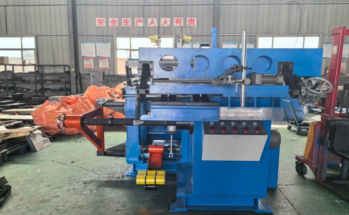
Supports winding preset parameters for different wire diameters, wire materials, and winding specifications. The visual touch control system enables quick parameter start-up, allowing coil winding to be easily completed without highly skilled technicians, reducing errors.
A round transformer winding machine rotates an approved mandrel to form conductors into cylindrical transformer coils according to the specified winding process.
Not necessarily. A round transformer winding machine normally produces cylindrical coils on a mandrel. Toroidal coils require a different winding process and dedicated machine structure.
Compatibility depends on the conductor material, shape, cross-section, insulation, reel arrangement, tension method, torque demand and coil geometry. Confirm the actual conductor before selecting the configuration.
Only when the proposed configuration includes the required pay-off units, tension components, guides and control functions. Multi-conductor winding should be demonstrated using representative materials during FAT.
It may support an approved range, but changing specifications can require a different mandrel, guide position, pay-off setup, tension setting and operating parameters.
No. Automation may apply only to selected functions such as speed control, turn counting, traversing or program storage. Manual and automatic operations should be listed separately in the quotation.

