Aluminum Busbar Bending Machines for Drawing-Defined Parts
FengHua provides aluminum busbar bending configurations for standard, recurring and multi-operation production. A model should be selected only after the material and finished geometry have been reviewed.
CNC control, hydraulic drive, automatic feeding and multi-station processing are different functions, and their availability varies by model. A CNC label describes the control method; it does not automatically mean that feeding, unloading, angle measurement or springback compensation is automatic. A hydraulic label describes the power method; it does not define accuracy.
Before recommending a machine, FengHua should review the aluminum alloy and temper, maximum dimensions, flatwise or edgewise bending direction, inside radius, finished angle, surface requirement, batch quantity and factory voltage.
Compare Aluminum Busbar Bending Machine Models
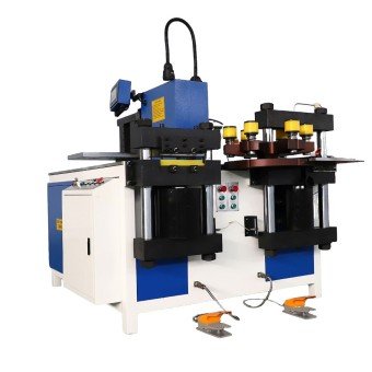
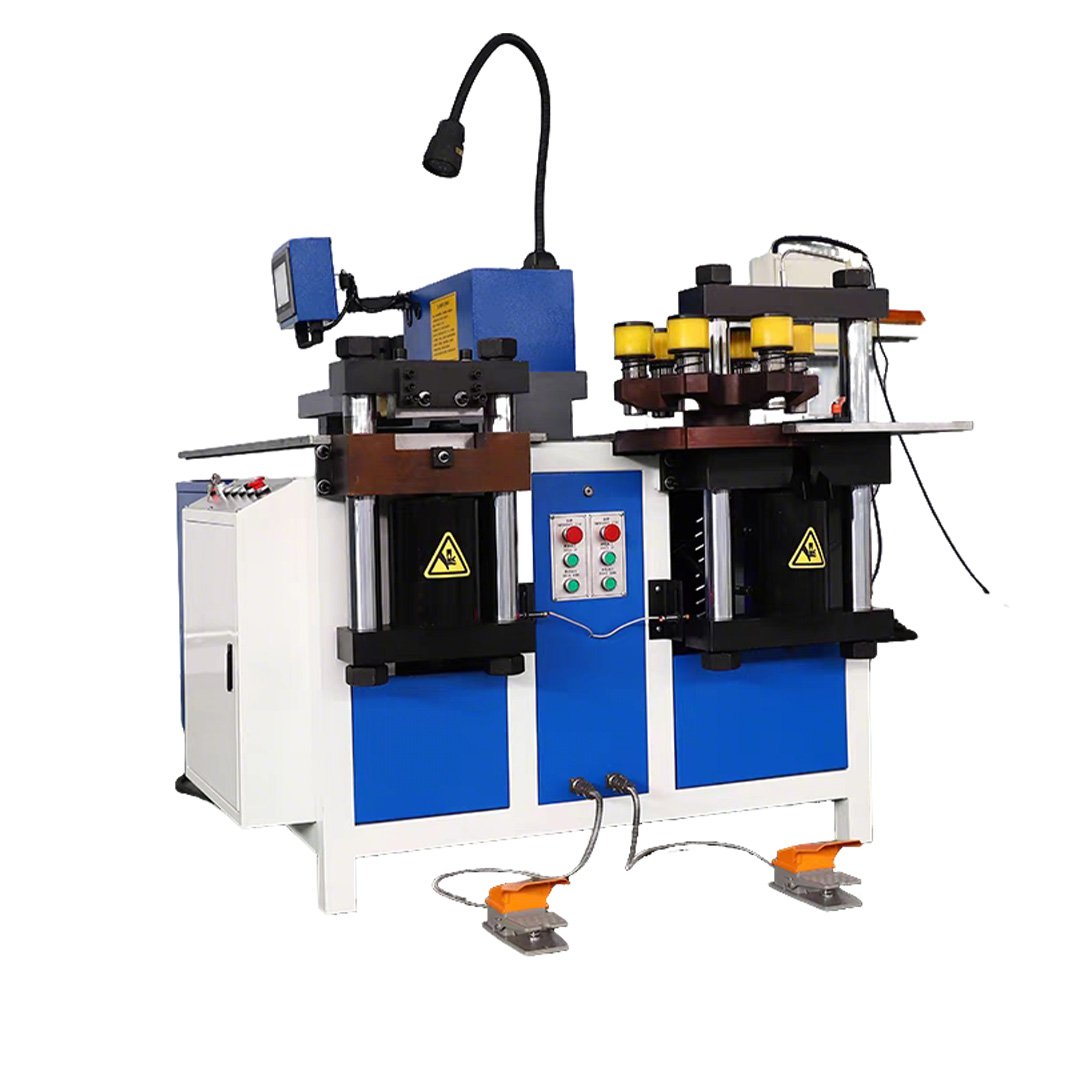
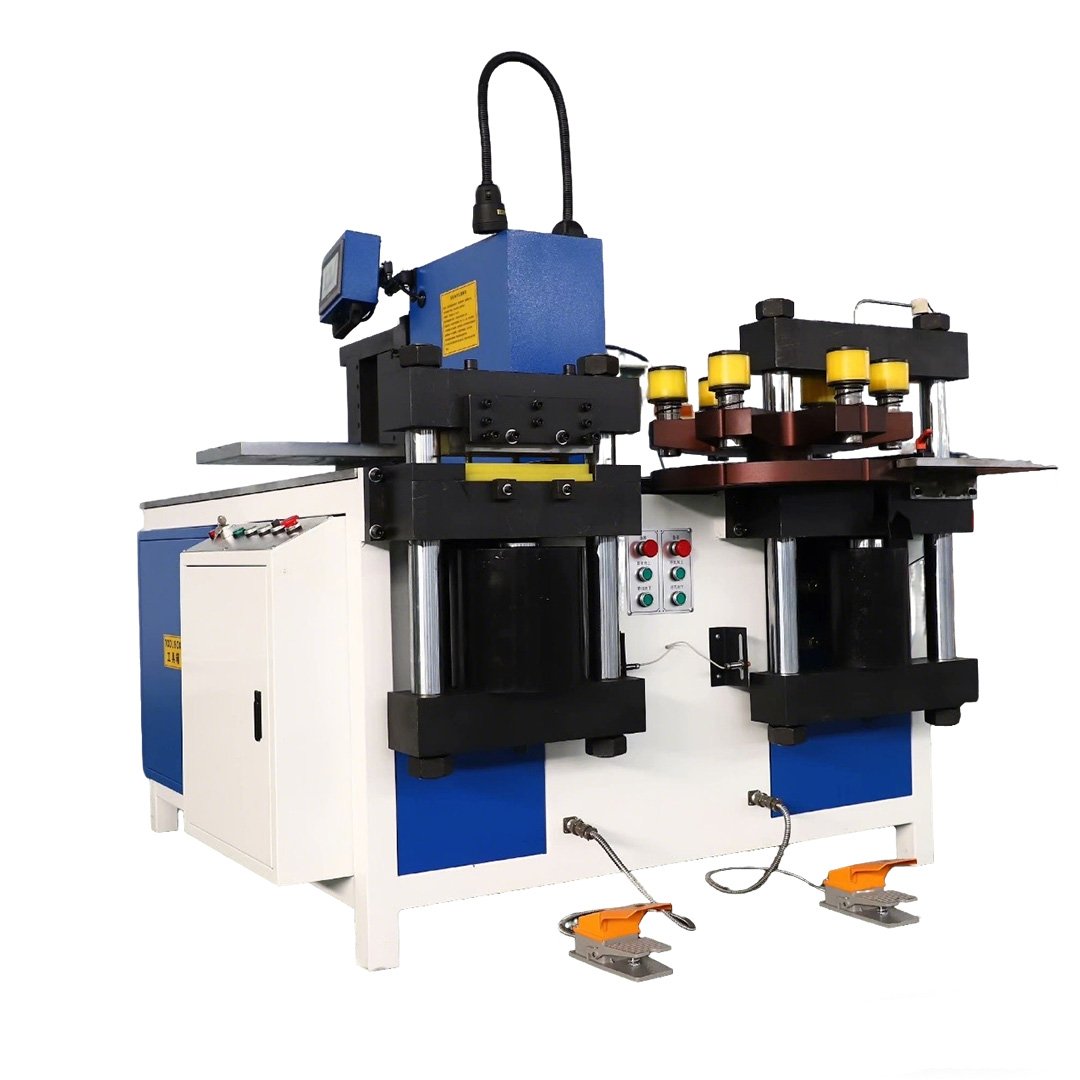
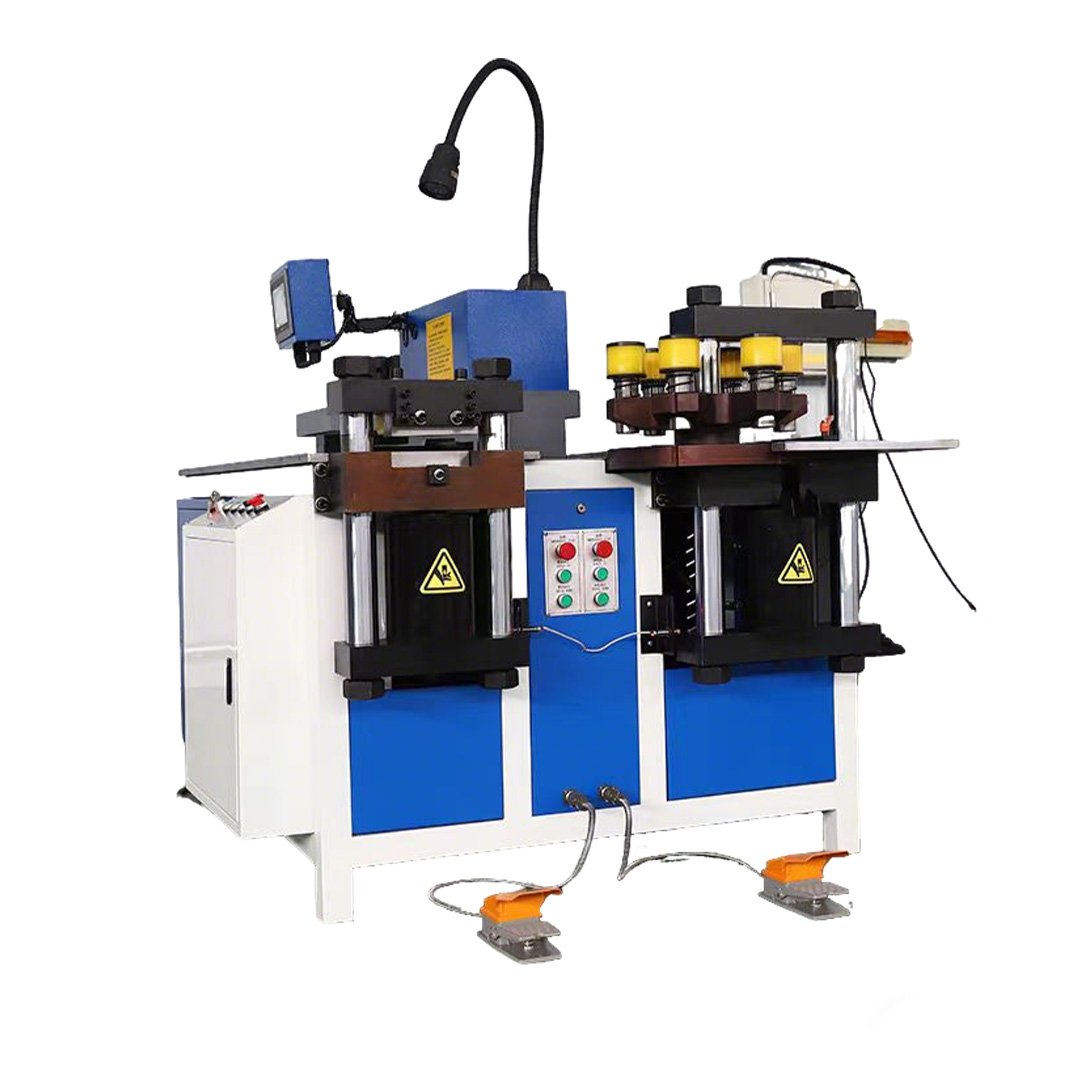
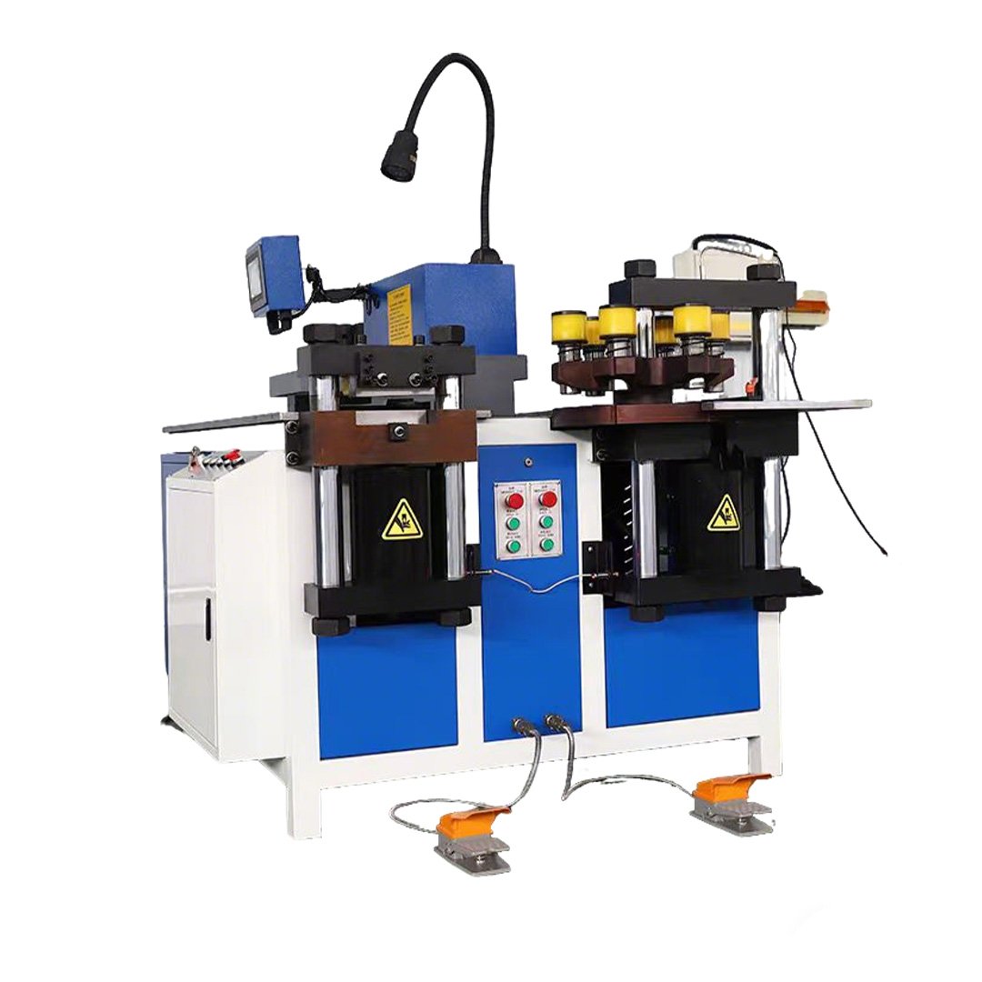
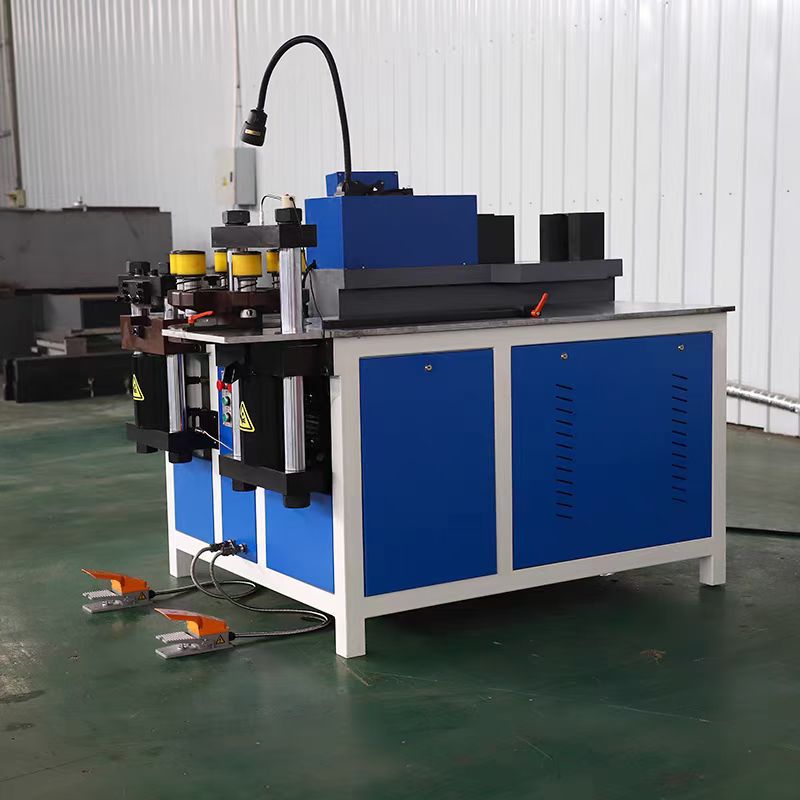
An integrated punching, shearing and bending configuration for mixed busbar production. Confirm the aluminum alloy and temper, maximum dimensions, bending direction, inside radius and required tooling before selection.
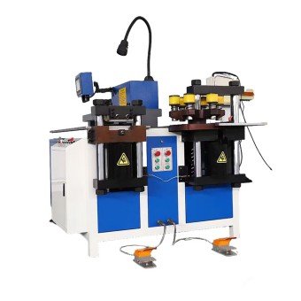
An integrated busbar processing configuration for drawing-based punching, shearing and bending. Confirm operation-specific aluminum capacity, tooling scope and representative sample requirements in the technical proposal.
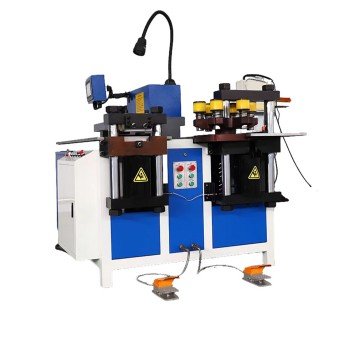
An integrated configuration for drawing-defined aluminum busbar processing. Confirm the bending orientation, tooling clearance, material-handling requirements and FAT sample conditions before ordering.
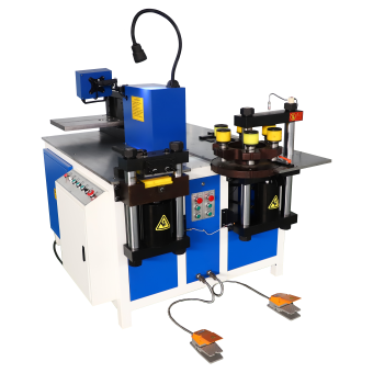
Compare multi-function aluminum busbar equipment when cutting and punching are required in addition to bending. Select the final model according to the material specification, complete drawing and required production workflow.
What to Confirm Before Selecting an Aluminum Busbar Bending Machine

Confirm the aluminum alloy, temper, dimensions and surface condition before machine and tooling selection.

Review the inside radius, bending direction, hole-to-bend distance and finished geometry before confirming the tooling.

Select the control and drive configuration according to the drawing variety, production workflow and verified model functions.

Confirm the bending result using the specified material, agreed drawing and documented measurement method before shipment.
How Repeatable Aluminum Busbar Bending Is Verified
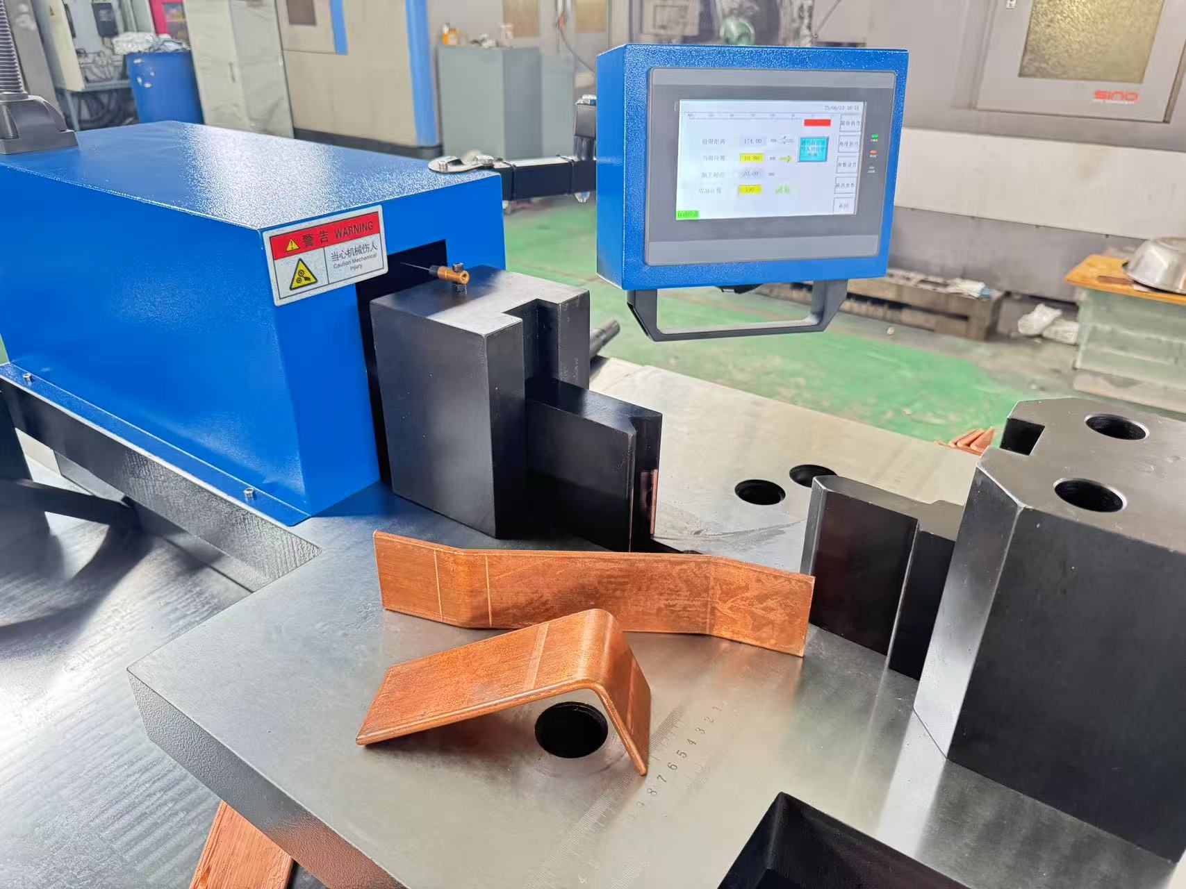
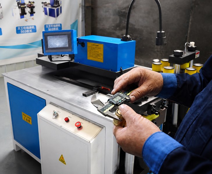
CNC positioning and reusable programs can reduce repeated manual input, but they do not by themselves guarantee the final angle or inside radius. Material variation, alloy and temper, springback, tooling condition, setup and first-piece correction still affect the finished result.
Before batch production, process a sample from the specified aluminum material, measure it using the agreed method and adjust the program when necessary. The approved material, tooling, program and measurement results should be recorded for recurring production.
Any published repeatability claim should identify the machine model, aluminum alloy and temper, dimensions, bending geometry, sample quantity and measurement method.
Efficient Batch Processing
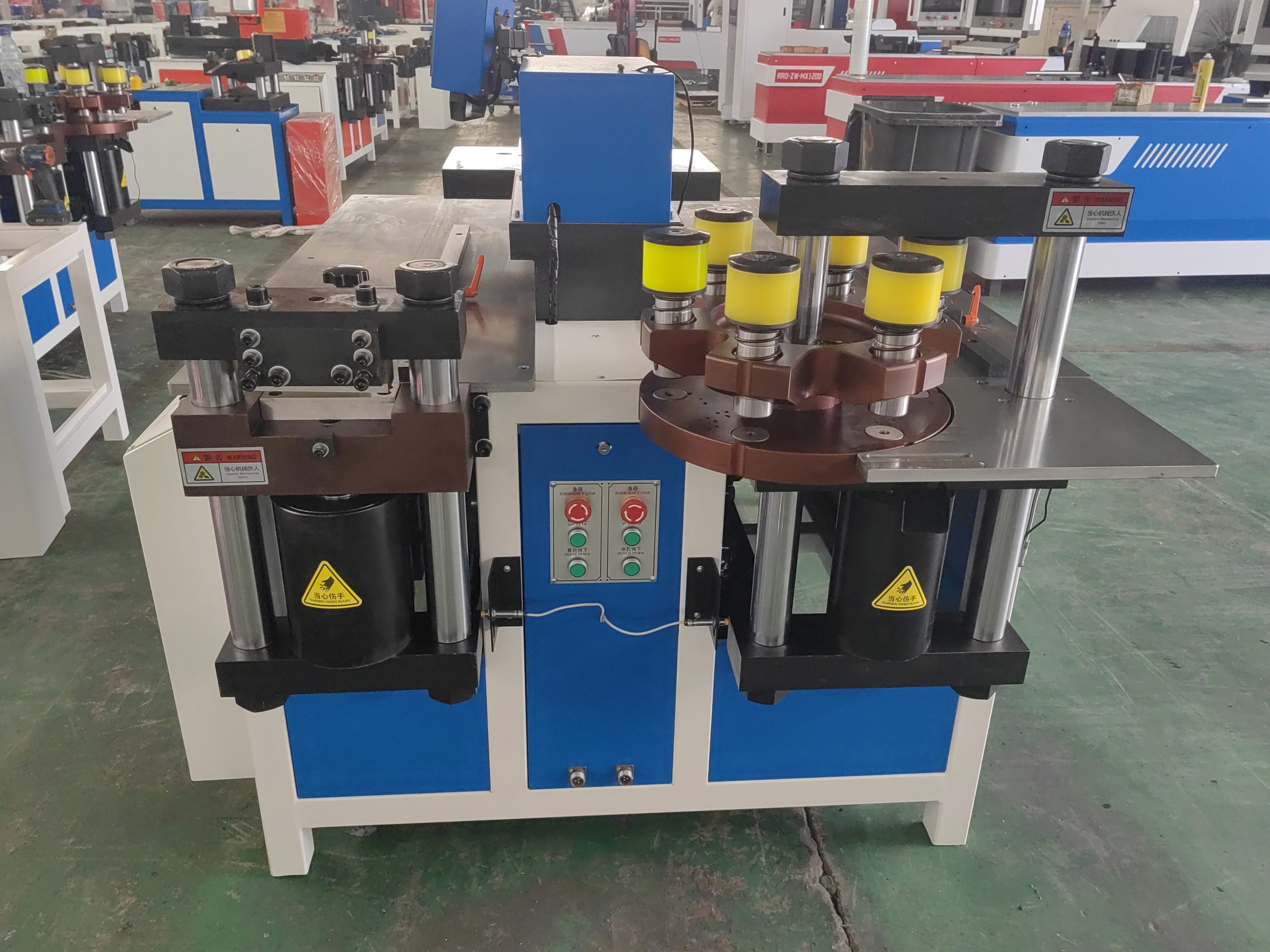
Stored and approved programs may reduce repeated data entry for recurring parts. Actual production improvement depends on material loading, positioning, tooling changes, first-piece correction, inspection, unloading and the number of different drawings processed in each batch.
Program storage does not mean that feeding, positioning, unloading or inspection is automatic. The automation boundary and complete cycle time should be demonstrated for the selected machine model.
Before ordering, compare the time from material loading to the first conforming part, rather than relying only on an individual bending-cycle time.
Machine and Tooling Configuration Based on Your Drawings
Before quotation, provide the aluminum alloy and temper, common and maximum dimensions, flatwise or edgewise bending direction, required angle, inside radius, bend sequence, surface requirement, drawing tolerances and production target.
FengHua should review the machine configuration, tooling access, possible interference, material handling and workshop requirements before confirming capability. Special offset, U-shaped, Z-shaped, short-leg or multi-bend parts require complete drawing review.
The final technical agreement should identify the machine model, applicable material, included tooling, control functions, electrical configuration, test items, documentation, excluded functions and service scope.
How to Compare Aluminum Busbar Bending Machine Manufacturers in China
There is no universally recognized official ranking of the top 10 busbar machine manufacturers in China. When comparing suppliers, evaluate model-specific bending capacity, supported aluminum grades and tempers, tooling scope, released-angle test results, sample quality, factory acceptance procedures, documentation, warranty responsibilities and service availability in your destination country.
FengHua publishes “10 Busbar Machine Manufacturers in China to Compare” as a buyer research guide. It is not an independent certification, and the order should not be interpreted as a quality ranking. Buyers should verify every supplier against their own drawings, material and acceptance requirements.
Stable, Precise, and Efficient Aluminum Busbar Bending
Why Aluminum Requires a Material-Specific Bending Review
| Buyer input | Why it matters |
|---|---|
| Alloy and temper | Affects strength、ductility、springback and suitable tooling |
| Width and thickness | Used with bend direction and radius to review capacity |
| Flatwise or edgewise bend | May require different force, clearance and tooling |
| Inside radius and angle | Affects tooling choice and finished geometry |
| Hole-to-bend distance | May create interference or deformation risks |
| Surface requirement | Determines acceptable clamping and tool-contact marks |
| Batch quantity | Affects program, inspection and material-handling requirements |
| Drawing tolerance | Defines the measurement and acceptance method |
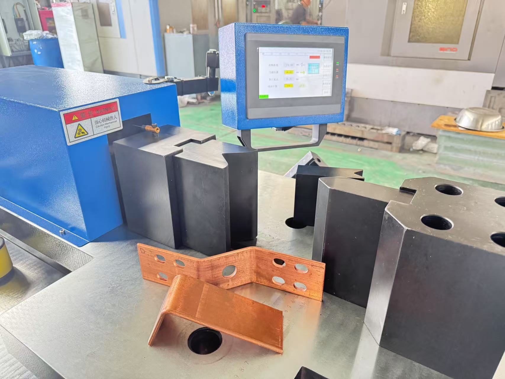
Machine suitability for repeated or multi-shift production depends on the selected model, hydraulic or servo configuration, duty cycle, cooling method, tooling condition, maintenance plan and material-handling workflow.
Before confirming a machine for continuous production, define the required conforming output, batch length, planned operating hours, changeover frequency and inspection method. These conditions should be included in the technical proposal and factory acceptance plan.
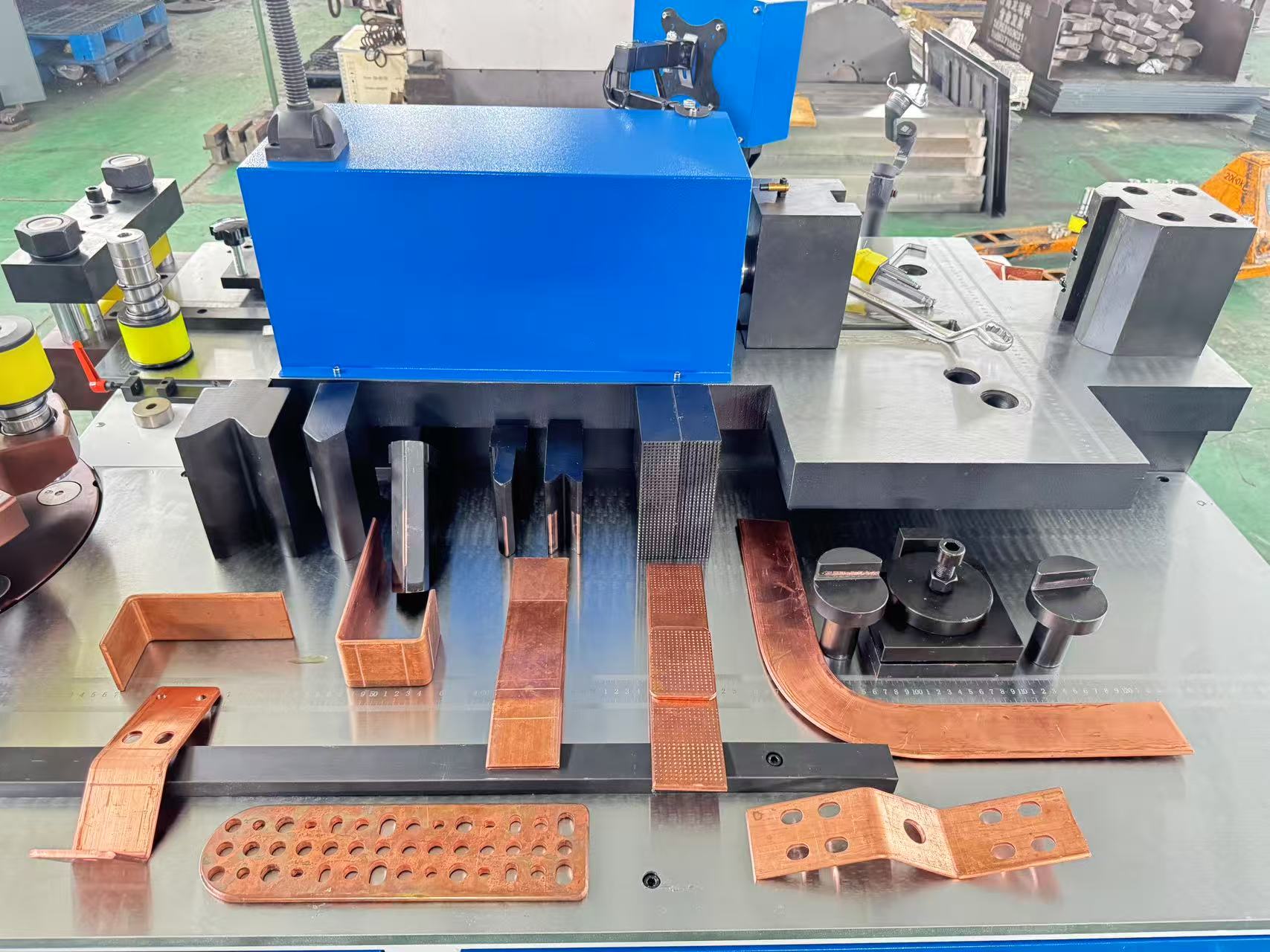
Aluminum surfaces may be marked by contaminated tooling, sharp contact edges, unsuitable clamping or incorrect alignment. If cosmetic, coated or film-protected surfaces are important, define the permitted marking level in the drawing or technical agreement.
Confirm the die-contact surfaces, protective-film compatibility, clamping method and sample-acceptance criteria before production. Appropriate tooling and material handling can help reduce surface marking, but scratch-free bending should not be promised without a defined surface requirement and verified sample.
Some configurations may process both materials, but capability must be confirmed separately for each material and operation. Do not apply a copper capacity or program directly to aluminum. Provide the alloy, temper, dimensions, bend drawing and required inside radius for evaluation.
No. CNC control improves program and positioning repeatability, but the final result is also affected by alloy, temper, material variation, springback, tooling, setup and first-piece correction. Confirm the result using an agreed sample and measurement method.
This depends on the part geometry, tooling clearance, bend sequence, inside radius and selected machine. Submit the complete drawing before the bend type is confirmed.
A stored program may support repeated production, but this does not necessarily mean that feeding, positioning, unloading or inspection is automatic. The automation scope must be confirmed for the selected model.
Use clean and suitable tooling, correct alignment, an appropriate clamping method and verified contact surfaces. If the busbar is coated or protected by film, state this before tooling selection and approve a sample before batch production.
Provide the alloy and temper, maximum and common dimensions, flatwise or edgewise bend, inside radius, finished geometry and production target. Capacity must be confirmed by material, operation and tooling rather than by width and thickness alone.
Confirm the exact model, applicable material, tooling list, control functions, electrical supply, machine layout, FAT items, documentation, spare parts, installation responsibilities, warranty and service coverage in the technical agreement.
Available installation, training, remote assistance and on-site support depend on the machine, destination and agreed project scope. The response method, responsibilities, included days and chargeable items should be stated in the quotation or contract.