
Quick Answer
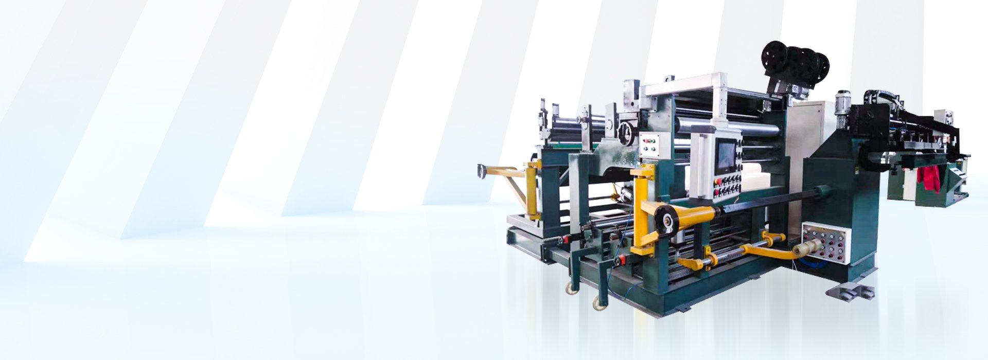
An aluminum foil winding machine winds aluminum foil conductors together with interlayer insulation onto an approved mandrel to produce transformer foil coils.
The required configuration depends on the aluminum alloy or temper, foil width and thickness, reel dimensions and weight, finished coil size, insulation, winding load, tension method, edge-alignment system, conductor-joining process and required automation.
CNC control, automatic foil feeding, closed-loop tension, automatic edge correction, insulation feeding and welding are separate configuration items. They should not be assumed to be included unless they are stated in the approved technical quotation.
What Is an Aluminum Foil Winding Machine?
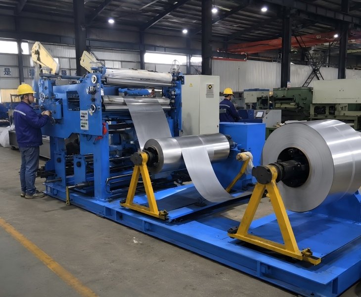
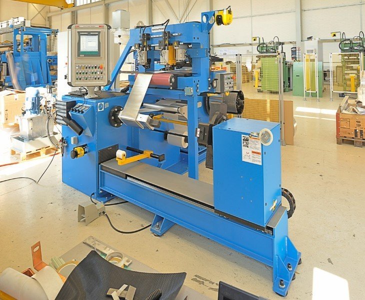
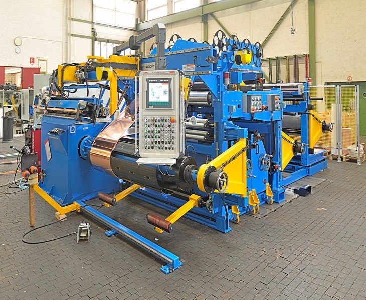
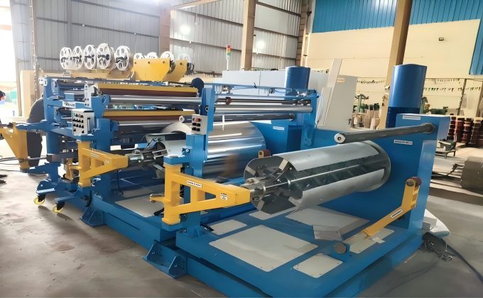
An aluminum foil winding machine combines a winding spindle, aluminum-foil decoiling system, insulation feeding, tension adjustment, edge-position control and mandrel support to produce transformer foil coils.
Unlike a conventional wire winding machine, the equipment must handle a wide, thin conductor while controlling reel movement, foil tension, edge position, insulation placement and conductor joining.
The exact process varies according to the approved coil design. Reel loading, foil threading, insulation placement, lead-bar positioning, joining, coil removal and inspection may remain manual even when selected winding functions are digitally controlled.
The technical quotation should identify every included system, controlled function, manual operation and unsupported requirement.
Aluminum Foil Winding Project Configurations
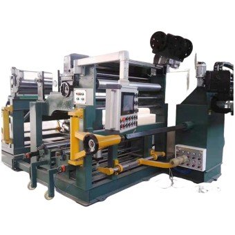
Configured for transformer projects using aluminum foil conductors and interlayer insulation. Confirm the foil specification, reel weight, coil dimensions, mandrel and required joining method.
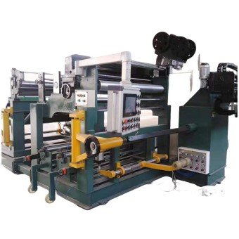
Reviewed for projects involving several aluminum-foil and insulation layers. Confirm the layer structure, reel arrangement, edge-alignment method, tension process and inspection requirements.
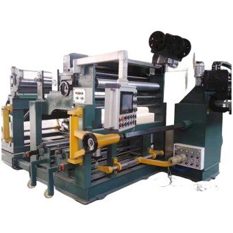
Used for dry-type transformer coils requiring approved aluminum foil, insulation, coil geometry, lead-bar arrangement and winding-process documentation.
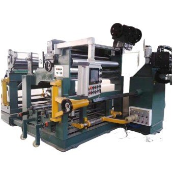
These cards describe project configurations rather than fixed machine models. The final equipment should be selected according to the approved aluminum foil, coil drawing, insulation, mandrel and FAT requirements.
Systems to Confirm Before Selecting an Aluminum Foil Winding Machine

Confirm the aluminum-foil reel dimensions, reel weight, shaft or chuck interface, loading method, braking method, decoiling direction and material-support arrangement.

Confirm the tension-control principle, adjustment method, sensing system, edge-correction method and operating procedure for the approved aluminum foil and winding speed.

Confirm the insulation material, width, thickness, reel arrangement, feeding method, overlap requirement and whether placement is automatic, assisted or manual.

Confirm the approved aluminum-foil joining method, lead-bar design, included equipment, process sequence, inspection method and operator responsibilities.
How Should Multi-Layer Aluminum Foil Winding Be Confirmed?
Multi-layer foil winding requires coordinated movement of the winding spindle, aluminum-foil reel, insulation reel, tension system and edge-position control.
The quotation should state how many aluminum-foil and insulation layers are supported by the proposed configuration and whether every layer uses independent or shared handling components.
During sample winding, inspect the foil-edge position, insulation placement, layer sequence, coil dimensions, surface condition and any visible foil movement against the approved winding plan.
Multi-layer capability should be verified using the customer’s representative aluminum foil and insulation rather than confirmed only from the machine name.
Managing Different Aluminum Foil and Coil Specifications
Producing different aluminum-foil coils may require adjustments to the decoiler, reel shaft, braking method, tension settings, edge guide, insulation reels, mandrel, joining setup and operating parameters.
The technical quotation should identify the supported aluminum-foil range, required tooling and changeover procedure.
For mixed-specification production, include a practical changeover and sample-winding test during FAT to verify the adjustment steps, setup time and finished-coil results.
How Should Aluminum Foil Tension Be Confirmed?
Tension performance should be defined according to the proposed control system rather than described only as stable or automatic.
Confirm the tension-control principle, adjustment method, feedback components and operating procedure against the aluminum alloy or temper, foil dimensions, reel condition, winding speed, coil geometry and insulation process.
During FAT, use representative aluminum foil and reel conditions. Record the tension settings, operating speed, foil-edge position, surface condition and finished-coil results.
Do not publish a tension range or tension accuracy until the exact components, measurement method and acceptance limits are confirmed.
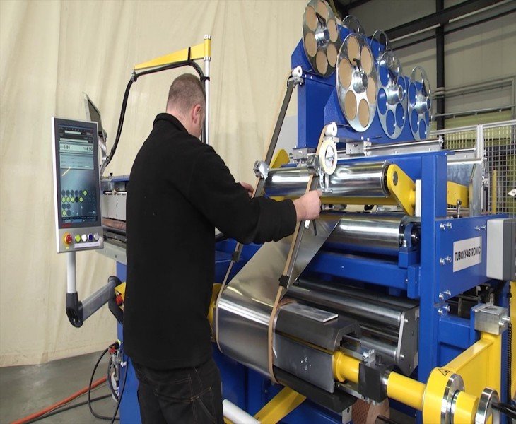
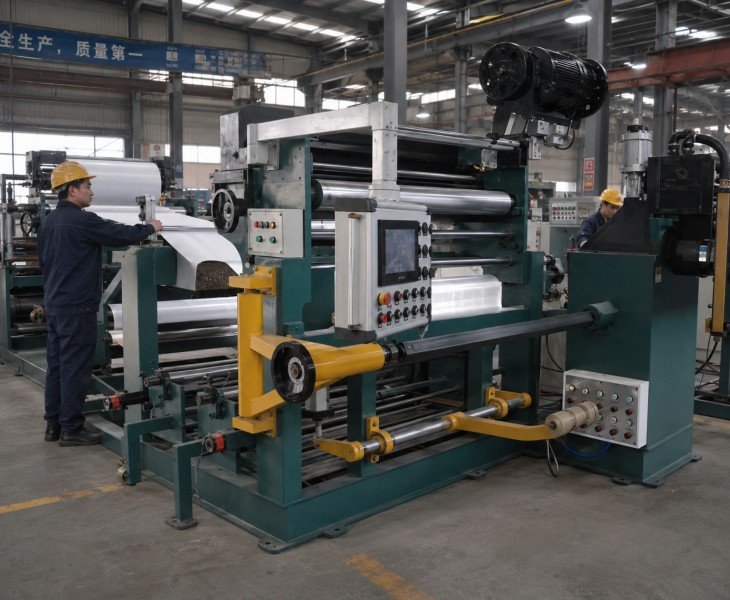
Aluminum Foil Winding Machine FAT Checklist
| FAT Check | What to Verify | Evidence |
|---|---|---|
| Configuration and Safety | Machine matches the quotation and contracted protection operates | Configuration sheet and checklist |
| Aluminum Foil and Reel | Approved foil, reel loading, decoiling and braking | Test record and video |
| Tension, Edge and Insulation | Settings, foil position and insulation placement | Settings and sample coil |
| Joining, Leads and Coil | Joining process, lead position, dimensions and surface | Inspection report and photos |
| Documents and Spare Parts | Manuals, drawings, component list and contracted parts | Document index and packing list |
Agree the aluminum foil, insulation, reel, mandrel, joining process, sample quantity, measuring instruments and acceptance limits before FAT.
How to Compare China’s Top 10 Transformer Winding Machine Manufacturers for Aluminum Foil Projects
Use a top-10 manufacturer list as an initial sourcing shortlist rather than proof that a proposed machine is suitable for your aluminum foil coil.
For an aluminum foil winding project, compare the exact configuration proposed for your foil, reel, coil drawing, insulation and joining process rather than relying only on company size, automation claims or promotional rankings.
| Comparison Factor | What to Confirm | Evidence to Request |
|---|---|---|
| Aluminum Foil Capability | Foil range, reel handling and coil capacity | Signed specification and layout |
| Winding Process | Tension, edge alignment and insulation feeding | Function list and demonstration |
| Joining and Sample Coil | Lead bars, joining process and finished coil | Sample and inspection report |
| FAT and Service | Acceptance, documents, warranty and spare parts | Signed FAT and service scope |
Final supplier selection should be based on the approved machine configuration, representative aluminum-foil winding test, FAT evidence and contract terms.
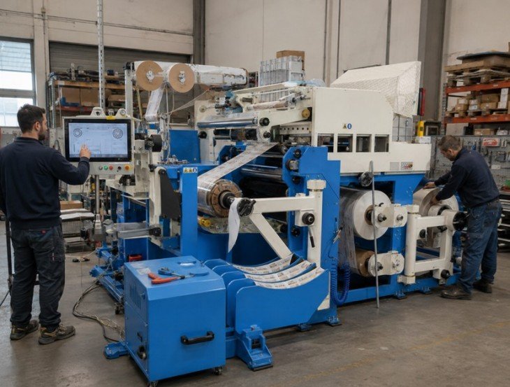
Stable Winding and Precise Insulation Synchronization
Achieve high-quality aluminum foil coil production on your production line through foil correction and automatic insulation laying.
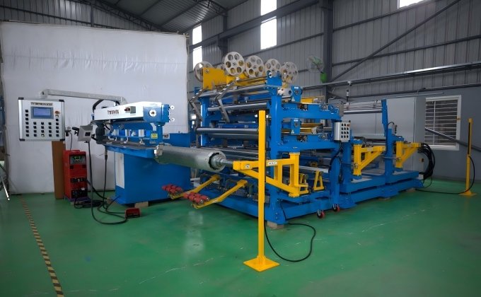
Confirm whether the proposed configuration uses manual adjustment, mechanical guiding, sensor-based correction or another approved method.
During sample winding, measure the foil-edge position and finished coil profile using the approved aluminum foil and insulation.
The quotation should identify the sensor, correction range, adjustment method and operations that remain manual.
Confirm the insulation material, width, thickness, reel dimensions, feeding method, overlap and tension requirements.
During sample winding, inspect the insulation position, overlap, layer sequence, visible damage and relationship to the aluminum-foil edge.
Do not describe insulation placement as automatic unless the proposed feeding system and control functions are included in the approved configuration.
An aluminum foil winding machine winds aluminum foil conductors and interlayer insulation onto an approved mandrel to produce transformer foil coils.
There is no universal range for every configuration. Confirm the aluminum alloy or temper, foil width and thickness, reel dimensions, reel weight, coil drawing and winding load before selection.
It may support an approved range, but changes can require adjustments to the reel shaft, braking method, tension settings, edge guide, insulation reels, mandrel and operating parameters.
Multi-layer capability depends on the number of conductor and insulation layers, reel arrangement, tension system, edge alignment and proposed machine configuration. Verify it using representative materials during FAT.
Not in every machine. Confirm the sensing, correction and adjustment method, and verify the foil-edge position using the approved aluminum foil and insulation.
The joining method depends on the coil design and approved process. Confirm the required equipment, materials, joint preparation, operating sequence and inspection criteria.
No. Automation may apply only to selected functions. Reel loading, threading, insulation setup, lead positioning, joining, coil removal and inspection may remain manual.
No. Sample winding can verify the machine configuration and winding process. Transformer electrical performance must be verified through separate coil and transformer testing.
Provide the aluminum foil, reel, coil drawing, winding load, insulation, mandrel, lead bars, joining method, output, voltage, automation and FAT requirements.
Use the approved aluminum foil, insulation, reel, mandrel and joining process to verify winding, tension, edge alignment, insulation placement, coil dimensions, safety, documents and spare parts.

