
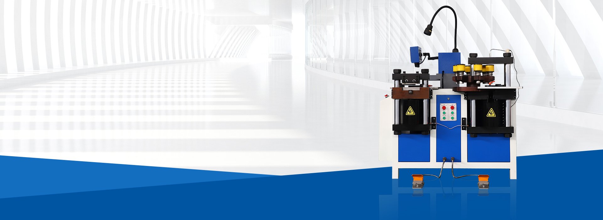
Quick Answer: How Should You Select a Copper Busbar Punching Machine?
Select a copper busbar punching machine according to the copper grade and temper, maximum width × thickness, raw-bar length, hole and slot geometry, hole-center pitch, hole-to-edge distance, tooling, positioning method, required output and FAT criteria.
Do not select a machine only by punching force, maximum busbar size or the word “CNC.” Confirm whether every required hole can be reached and punched through the specified material with the approved die.
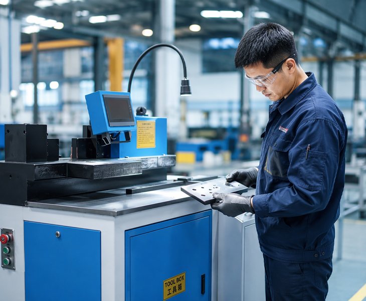
Copper Busbar Punching Machine Manufacturer for Drawing-Based Production
FengHua configures copper busbar punching equipment according to the finished hole layout rather than only the nominal punching force.
Before quotation, the engineering review should confirm the copper grade and temper, regular and maximum width × thickness, raw-bar length, round-hole diameter, slot length and width, hole-center pitch, hole-to-edge distance, datum, required tolerance, and batch quantity.
The technical quotation should identify the exact machine model, punching-station capacity, positioning method, included dies, optional dies, manual and automatic operations, electrical configuration, FAT samples, documentation, warranty and recommended spare parts.
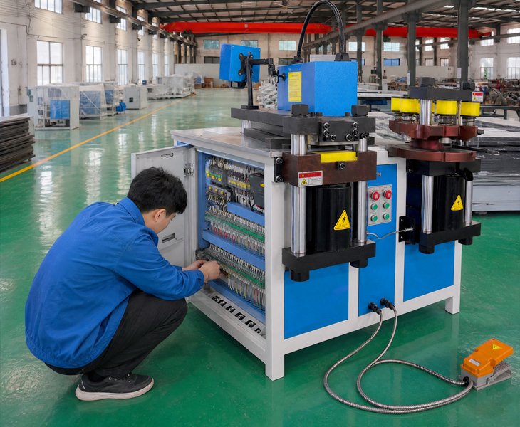
Fenghua CNC Copper Busbar Punching Machine Product Solutions
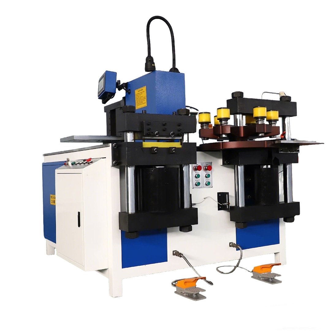
An integrated punching, cutting and bending configuration with a published overall processing reference of 160 × 16 mm, a Ø4.3–34 mm punch range and 350 kN punching force.
- Overall source-sheet reference: 160 × 16 mm
- Punch range: Ø4.3–34 mm
- Punching force: 350 kN
- Motor configuration: 3 × 4 kW
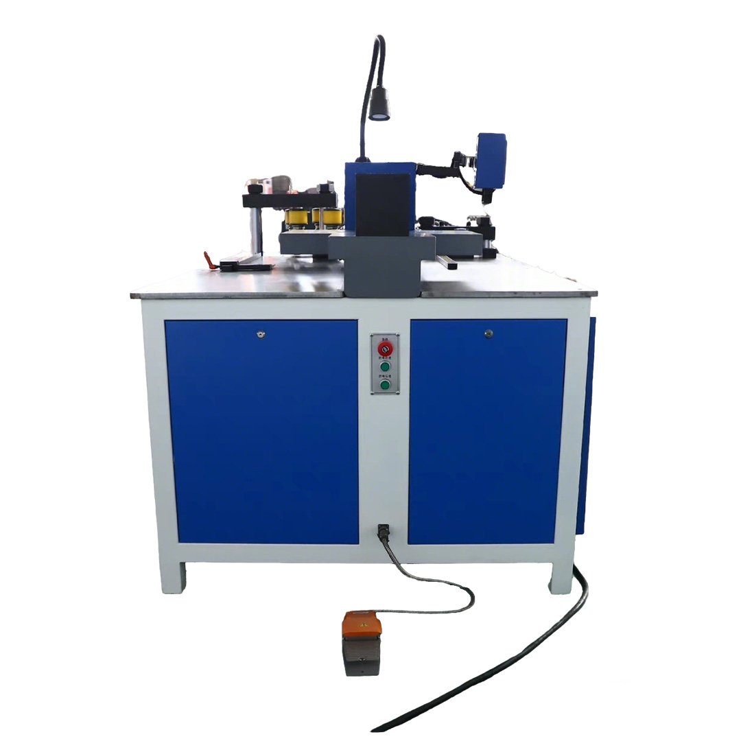
A medium-capacity integrated configuration with punching, cutting and bending stations, a published overall processing reference of 260 × 16 mm and 500 kN punching force.
- Overall source-sheet reference: 260 × 16 mm
- Punch range: Ø4.3–34 mm
- Punching force: 500 kN
- Motor configuration: 3 × 5.5 kW
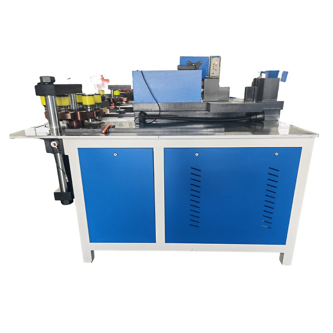
The highest-capacity model in the uploaded GJBM series, with a published overall processing reference of 300 × 20 mm and 800 kN punching force.
- Overall source-sheet reference: 300 × 20 mm
- Punch range: Ø4.3–34 mm
- Punching force: 800 kN
- Motor configuration: 3 × 7.5 kW
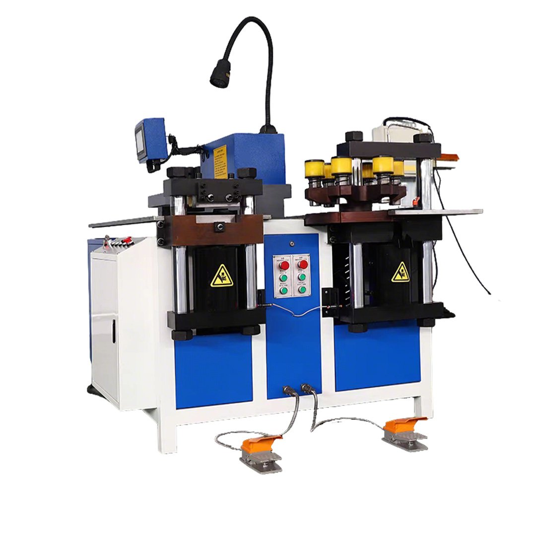
For projects requiring round holes, slots, oblong holes or drawing-specific profiles. Tooling feasibility depends on the copper thickness, hole dimensions, hole-to-edge distance, pitch and required finished quality.
Which GJBM Copper Busbar Machine Should You Choose?
| Production Requirement | Starting Model | Main Check |
|---|---|---|
| Overall size within 160 × 16 mm | GJBM303 | Punching capacity and required dies |
| Overall size up to 260 × 16 mm | GJBM503 | Hole geometry and material thickness |
| Overall size up to 300 × 20 mm | GJBM803 | Maximum-size sample and handling |
| Special hole profiles | Custom tooling solution | Edge distance, pitch and die feasibility |
The dimensions above are overall model-level references from the source sheet. Confirm the punching capacity of each required die separately.
GJBM Series Integrated Punching Specifications
| Model | Overall W × T | Punch Range | Punching Force | Motor | Weight |
|---|---|---|---|---|---|
| GJBM303 | 160 × 16 mm | Ø4.3–34 mm | 350 kN | 3 × 4 kW | 1,300 kg |
| GJBM503 | 260 × 16 mm | Ø4.3–34 mm | 500 kN | 3 × 5.5 kW | 1,800 kg |
| GJBM803 | 300 × 20 mm | Ø4.3–34 mm | 800 kN | 3 × 7.5 kW | 2,300 kg |
These GJBM models combine punching, cutting and bending. The published width and thickness values are overall source-sheet references and do not prove that every punching die can process the same maximum material size.
Confirm the copper grade and temper, hole or slot dimensions, applicable die, minimum edge distance and supported material thickness for each required operation.
- GJBM303: 1,780 × 1,400 × 1,400 mm
- GJBM503: 1,800 × 1,500 × 1,300 mm
- GJBM803: 1,950 × 1,550 × 1,200 mm
- Source-sheet voltage: 380 V
The uploaded source sheet lists a three-year warranty, available video factory inspection, available mechanical test reports and standard wooden-case packaging.
The final warranty agreement should define covered components, exclusions, service method and international freight responsibility.
What Should You Confirm in a Copper Busbar Punching Machine?

Confirm the round and slotted-hole dimensions, X and Y coordinates, hole-center pitch, hole-to-edge distance and the datum used for inspection.

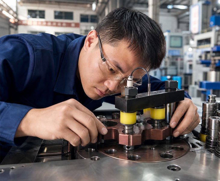
Confirm the included dies, applicable copper thickness for each die, die clearance, custom-tooling availability and replacement lead time.

Confirm how the busbar is positioned, the effective range, clamp or fixture clearance, short-part handling and any inaccessible or dead-zone areas.

Confirm hole geometry, burr condition, surface marks, deformation, punch and die inspection intervals and recommended spare tooling.
Custom Copper Busbar Punching Machine Solutions
A custom copper busbar punching configuration should begin with the complete hole drawing.
FengHua reviews the copper grade and temper, width × thickness, raw-bar length, hole and slot geometry, minimum edge distance, pitch, datum, batch quantity, positioning method and required finished quality.
The approved quotation should identify the machine model, included dies, optional dies, custom-tooling drawings, applicable material thickness, die-change method, spare punches and dies, FAT samples and inspection criteria.
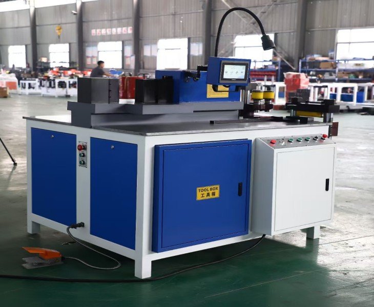
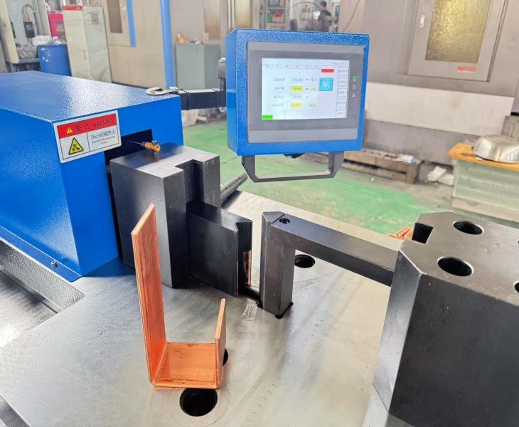
How to Achieve Accurate Copper Busbar Punching
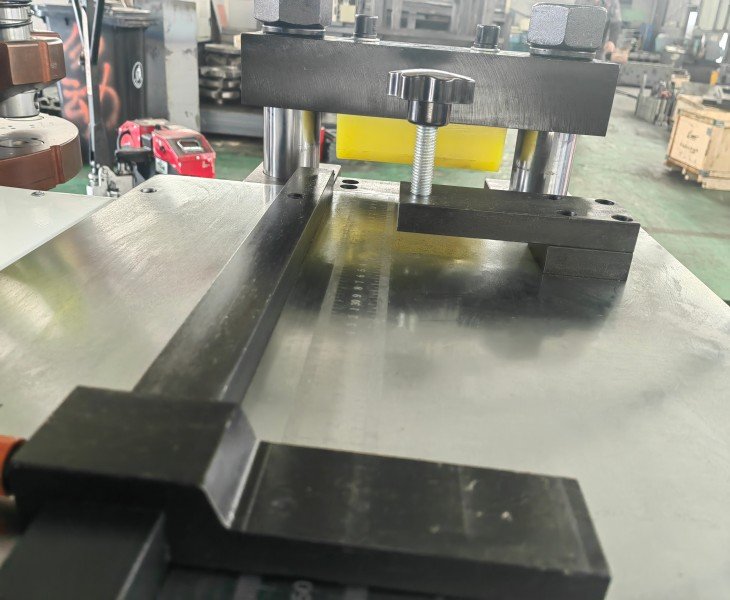
The Copper Busbar Punching Machine developed by Fenghua CNC combines a precision positioning system with a stable punching mold structure to ensure reliable punching accuracy.
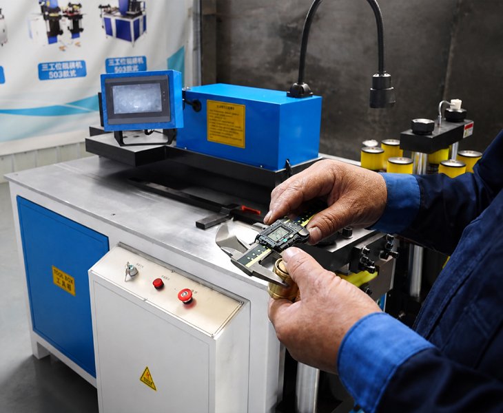
During operation, operators only need to set the punching position and hole parameters through the control interface. The equipment automatically completes the punching process according to preset specifications.
In traditional busbar processing workshops, manual drilling or marking often causes inconsistent hole spacing. With a CNC busbar punching machine, the punching process is repeatable, reducing the risk of installation problems during your production line electrical assembly.
Fast Copper Busbar Punching for Industrial Production
Fenghua CNC automatic copper busbar punching machines punching speed even during long production cycles. For manufacturers producing busbars for large distribution systems or switchgear cabinets.
Industry reports show that a typical electrical panel manufacturing factory may process hundreds of busbars per day, each requiring multiple connection holes. Using automated punching equipment improves your production line efficiency.
With optimized punching structures and reliable drive systems, the machine helps your efficiency reduce production bottlenecks in busbar processing lines.
Copper Busbar Punching Applications
| Application | Typical Hole Requirement | Main Check |
|---|---|---|
| Switchgear | Breaker and terminal connections | Hole datum and assembly position |
| Electrical Panels | Repeated component layouts | Program or positioning repeatability |
| Transformers | Drawing-specific conductor links | Material thickness and die |
| Busduct Systems | Repeated joint connections | Pitch, edge distance and output |
| Energy Storage Cabinets | Compact connection layouts | Short-part handling and surface quality |
How to Compare China’s Top Copper Busbar Punching Machine Manufacturers
There is no single official ranking that certifies the ten best copper busbar punching machine manufacturers in China.
A Top 10 list should be used as a supplier-research starting point rather than proof of punching accuracy, tooling capability or service quality.
Compare the exact proposed model, copper range, punching force, hole and slot tooling, positioning method, unreachable areas, sample results, FAT records, documentation, warranty and spare-parts support.
| Supplier Check | Evidence |
|---|---|
| Exact Model | Nameplate and configuration |
| Capability | Copper size, holes and dies |
| Positioning | Controlled axes and manual tasks |
| Testing | Samples and FAT results |
| Support | Documents and spare parts |
Copper Busbar Punching Machine FAT Checklist
| FAT Check | What to Confirm |
|---|---|
| Machine | Model and approved configuration |
| Material | Copper grade, size and drawing |
| Tooling | Included dies and hole range |
| Results | Position, geometry and repeatability |
| Acceptance | Safety, documents and sign-off |
Do not approve the machine after one successful hole. Test representative hole patterns, maximum required material and multiple consecutive finished parts.
How Are Multiple Hole Patterns Processed?
A programmed or positioned punching process can produce several hole coordinates on one busbar in sequence. This does not necessarily mean that several holes are punched at exactly the same time.
Confirm whether the approved machine uses one punching die, several fixed die stations, a rotary die arrangement or manual die changes. Also confirm whether the workpiece must be repositioned when the hole pattern exceeds the effective positioning range.
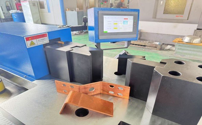
The machine supports various copper busbar sizes for equipment manufacturing, allowing workshops to process multiple product types with one punching system.
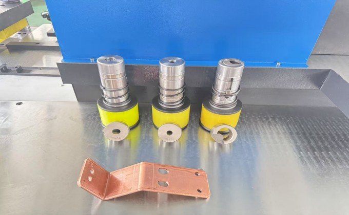
The equipment is equipped with an intuitive control interface that sets punching positions, hole spacing, and processing parameters, and improves your Finished product consistency.
It produces connection holes and slots in copper busbars used in switchgear, electrical panels, transformers, busduct systems and other power equipment. Final capability depends on the machine, die and copper specification.
The uploaded GJBM source sheet lists a published punch range of Ø4.3–34 mm. Confirm the required hole or slot, applicable die and supported copper thickness before ordering.
Not automatically. The published width and thickness are overall model-level references. Each die must be confirmed against the copper material, thickness, hole geometry and punching force.
Slot, oblong and custom profiles can be evaluated through tooling review. Provide the complete dimensions, corner radii, pitch, edge distance and copper thickness.
No. Servo positioning accuracy describes machine movement. Finished-hole accuracy must be measured from the agreed drawing datum and can also be affected by tooling, material movement and die condition.
Provide the copper grade and temper, width × thickness, raw length, hole and slot drawings, pitch, edge distance, required tolerance, batch quantity, local voltage and preferred automation level.

