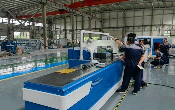
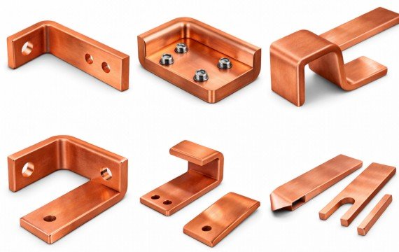
Busbar fabrication equipment for switchgear manufacturing should be selected from the approved busbar drawings, material specifications, required operations, assembly datums, production mix and finished-part acceptance criteria. A typical switchgear busbar may require cutting or shearing, punching, slotting, flat bending, edge bending, marking, deburring, inspection and handling between processes. The correct equipment configuration depends on which operations are repeated, which dimensions require controlled positioning and which tasks remain manual.
The busbar machine supports mechanical fabrication. It does not independently determine current-carrying capacity, phase spacing, electrical clearances or the approved switchgear arrangement.
Quick Answer
Choose busbar fabrication equipment from the material grade or alloy, temper, width × thickness, raw-bar length, hole and slot layout, cutting length, bend direction, inside radius, bend-line position, finished tolerances, batch mix and required conforming output.
A hydraulic 3-in-1 machine may suit mixed and lower-volume orders. A servo-positioning 3-in-1 machine may reduce repeated manual positioning for recurring parts. An automatic CNC punching and shearing line may suit long repetitive batches, while complex or repeated bending may require a dedicated programmable bender.
Confirm punching, shearing, flat-bending and edge-bending capacity separately. Final selection should be verified through representative switchgear drawings, sample processing and an agreed FAT.
How Should Switchgear Assembly Interfaces Be Reviewed?
| Assembly Interface | What Must Be Confirmed |
|---|---|
| Circuit Breaker or Switch | Terminal position, hole pattern, joint area and access |
| Incoming and Outgoing Terminals | Connection datum, finished orientation and installation clearance |
| Insulating Support | Support position, hole location and finished busbar height |
| Phase Arrangement | Approved mechanical position and assembly envelope |
| Cabinet Structure | Frame, partition, door and panel interference |
| Joint Surface | Contact area, flatness, surface condition and permitted tool marks |
| Existing Holes and Slots | Distance from bend lines and tooling-contact areas |
| Multiple Bends | Bend sequence, orientation and access for later operations |
| Installed Part | Dimensional inspection or trial assembly requirement |
The busbar drawing should identify the approved mechanical datums used for inspection and assembly. Where fit-up is critical, define whether acceptance will rely on dimensional measurement, an inspection fixture or trial assembly with the representative breaker, terminal or support.
What Should a Switchgear Busbar Drawing Define?
| Drawing Input | What Must Be Confirmed |
|---|---|
| Drawing Identity | Drawing number, revision and approval |
| Material | Copper grade or aluminum alloy and temper |
| Busbar Section | Width × thickness |
| Raw Material | Standard length, surface and batch identification |
| Cutting | Finished length and tolerance |
| Holes and Slots | Size, shape, quantity and position |
| Positioning Datum | Approved reference edge or feature |
| Bend Geometry | Flat bend, edge bend, offset or other form |
| Finished Bend | Released angle, inside radius and bend-line position |
| Short Leg | Minimum finished flange |
| Existing Features | Holes, slots and previous bends near tooling contact |
| Assembly Interface | Breaker, terminal, support or cabinet datum |
| Surface | Burr, indentation, scratches and coating requirements |
| Inspection | Instrument, sampling and acceptance criteria |
The supplier should review the complete drawing rather than only the maximum width, thickness or bending angle.
Which Busbar Fabrication Operations Are Required for Switchgear?
| Operation | Finished-Part Requirement | Equipment Check |
|---|---|---|
| Cutting or Shearing | Finished length, squareness, burr and deformation | Material-specific capacity and blade condition |
| Punching | Hole or slot size, position, edge distance and spacing | Die list, tooling reach and positioning method |
| Flat Bending | Released angle, radius, bend line and short leg | Tooling, springback method and clearance |
| Edge Bending | Direction, radius and finished geometry | Operation-specific force and machine clearance |
| Complex Bending | Multiple bends and assembly envelope | Bend sequence and interference review |
| Marking | Part number, phase or project identification | Manual or automatic marking method |
| Deburring | Safe edges and acceptable surface | Included process or separate workstation |
| Handling | Loading, rotation, support and unloading | Operator count, rollers, crane and floor space |
| Inspection | Finished dimensions and batch comparison | Instruments, frequency and result records |
Which Equipment Configuration Fits Switchgear Production?
| Production Requirement | Starting Configuration | Critical Buyer Check |
|---|---|---|
| Customized panels and lower volume | Separate hydraulic machines or hydraulic 3-in-1 machine | Operation-specific capacity, tooling and positioning time |
| Mixed recurring switchgear models | Servo-positioning 3-in-1 machine | Controlled axes, program recall and remaining manual tasks |
| Repeated holes and fixed cutting lengths | Automatic CNC punching and shearing line | Feeding range, gripper dead zone, nesting and output |
| Complex or repeated bending | Dedicated programmable busbar bender | Tooling clearance, short leg, springback and repeated results |
| High parallel workload | Separate dedicated punching, cutting and bending stations | Operator allocation, queue time and station utilization |
| Wide, thick or long busbars | Heavy-duty equipment with external support | Capacity by operation, floor clearance and maximum-size test |
These configurations are starting points rather than fixed rules. One machine may combine hydraulic force, CNC programming, servo positioning and manual material handling. Confirm every supplied function separately.
How Should Operation-Specific Capacity Be Verified?
| Operation | Confirm Before Ordering | Common Procurement Risk |
|---|---|---|
| Punching | Material, width × thickness, hole, slot, edge distance and die reach | Hole layout cannot be completed |
| Shearing | Material, width × thickness, length, tolerance, burr and deformation | Rated capacity does not produce an acceptable cut |
| Flat Bending | Section, angle, radius, bend line, short leg and tooling | Angle error or tooling interference |
| Edge Bending | Section, direction, radius and machine clearance | Capacity insufficient for the operation |
| Complex Bending | Sequence, spacing, existing holes and finished envelope | Formed part collides with machine or tooling |
| Handling | Raw length, finished size, weight and support | Workpiece cannot be safely loaded or rotated |
| Inspection | Tolerance, instruments, sampling and records | Machine runs but conformity cannot be proven |
A published maximum width × thickness should not be applied automatically to every operation. Record the confirmed limits of punching, shearing, flat bending and edge bending separately in the quotation and FAT plan.
How Should Conforming Output Be Estimated?
| Cycle Element | What to Measure |
|---|---|
| Material Loading | Reel, rack or bar-loading time |
| Drawing and Program Selection | Revision and setup time |
| Tooling Setup | Punching, cutting and bending tool change |
| Positioning | Manual, digital, servo or automatic positioning |
| Processing | Actual punching, shearing and bending time |
| Rotation and Transfer | Movement between stations or machines |
| Inspection | First-part and in-process measurement |
| Rework | Correction, scrap and reprocessing time |
| Unloading | Finished-part removal and identification |
| Changeover | Last accepted Part A to first accepted Part B |
Estimate output from conforming finished parts per shift, not from one unloaded machine cycle. Record the operator count, material handling, inspection frequency and changeover time used in the calculation.
What Do Hydraulic, CNC, Servo, Automatic and Integrated Mean?
| Term | What It Describes | What It Does Not Prove |
|---|---|---|
| Hydraulic | How processing force is generated | Positioning method, automatic feeding or finished-part accuracy |
| CNC | How selected axes or parameters are programmed and controlled | Control of every machine function |
| Servo | Feedback control of a specified positioning or motion axis | Automatic loading, rotation or inspection |
| Automatic | The included degree of feeding, positioning, processing and unloading | Suitability for every drawing or batch mix |
| 3-in-1 | Punching, shearing and bending stations integrated into one machine | One-clamp automatic processing or automatic material transfer |
| Integrated Line | Several processing functions connected within an approved material flow | Elimination of every manual task or transfer |
| Programmable Bender | Stored or controlled bending-related settings | Automatic springback correction for every material batch |
A hydraulic 3-in-1 machine may also use CNC programming or servo positioning while retaining manual loading and longitudinal material movement.
Compare the controlled variables, material path, operator tasks and measured finished parts rather than relying only on equipment labels.
How Should the Total Cost of Busbar Fabrication Equipment Be Compared?
| Cost Area | What to Compare |
|---|---|
| Equipment | Machine, optional functions and accessories |
| Tooling | Standard dies, custom dies and replacements |
| Installation | Foundation, power, oil, air and commissioning |
| Labor | Operators required for the complete workflow |
| Setup | Programming, positioning and tooling change |
| Handling | Rollers, cranes, racks and material movement |
| Inspection | Instruments, sampling and record keeping |
| Material Loss | Scrap, test pieces and rework |
| Maintenance | Hydraulic, electrical, tooling and consumables |
| Spare Parts | Recommended stock and replacement lead time |
| Support | Training, remote support and on-site service |
| Production | Conforming parts per shift under the agreed mix |
Do not claim a lower total cost without recording the assumptions used for production mix, labor, tooling, changeover and acceptable output.
When Should You Review or Upgrade the Equipment Configuration?
| Observed Condition | What to Verify Before Upgrading |
|---|---|
| Increasing assembly correction | Finished cutting, punching and bending measurements |
| Repeat batches no longer match | Drawing, material, tooling and program revisions |
| Excessive operator dependency | Which positioning and handling tasks remain manual |
| Long production queues | Station utilization and actual bottleneck |
| High changeover time | Tooling, program and first-part approval breakdown |
| Frequent scrap | Verified defect cause and affected operation |
| Long busbars are difficult to process | Support, floor space and operator handling |
| Current equipment cannot complete drawings | Operation-specific capacity and interference |
| Output remains below target | Complete conforming cycle and operator count |
Upgrade only after identifying the verified constraint. Adding CNC control will not solve a tooling, material-handling, capacity or inspection problem that remains unchanged.
Frequently Asked Questions
What Information Is Required Before Selecting Busbar Fabrication Equipment?
Provide the approved switchgear busbar drawings, material grade or alloy, temper, width × thickness, raw-bar length, hole and slot details, cutting lengths, bend directions, inside radii, finished tolerances, batch quantities and required output. These inputs allow the supplier to review each operation separately.
Is a 3-in-1 Busbar Machine the Same as an Automatic Production Line?
No. A 3-in-1 machine integrates punching, shearing and bending stations within one machine frame. Material loading, longitudinal movement, rotation, positioning and inspection may remain manual unless the quotation explicitly includes automatic functions.
Does CNC Control Guarantee Conforming Busbar Parts?
No. CNC control can repeat the axes or parameters that are actually controlled. Material condition, tooling, support, springback, setup and inspection can still change the finished result. Verify conformity from measured completed parts.
When Are Separate Busbar Machines More Suitable?
Separate machines may be suitable when several operators need to work in parallel, individual operations have different cycle times, specialized tooling is required or the factory processes a high mix of customized switchgear parts.
How Should Output Be Compared Between Two Equipment Configurations?
Compare conforming finished parts per shift using the same drawing mix, material, operator count, tooling, inspection frequency and changeover assumptions. Do not compare only the advertised machine cycle.
What Should Be Tested Before Shipment?
Use common, maximum-size and complex switchgear busbar drawings to test punching, shearing, flat bending, edge bending, positioning, material handling, repeatability, changeover, safety and documentation. Record the hole positions, cutting lengths, released angles, bend-line positions, short-leg dimensions, first-middle-final comparison and unresolved issues in the FAT report.
Send Your Switchgear Busbar Drawings for Equipment Review
Provide one common production drawing, one maximum-size drawing and one complex drawing, together with the material, width × thickness, raw length, hole layout, cutting requirement, bend geometry, tolerances, batch mix and required conforming output.
Fenghua will review the required operations, equipment configuration, station capacities, positioning method, tooling, material handling, remaining manual tasks, complete production cycle and proposed FAT items. The written review should also identify optional, unsupported or excluded functions before the equipment configuration is approved. Send Switchgear Busbar Drawings for Machine, Tooling and FAT Review