
Intelligent 3-in-1 Busbar Machine for High-Efficiency Production
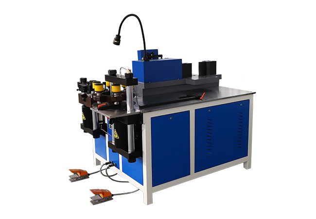
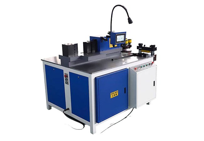
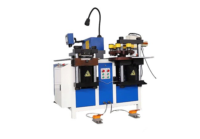
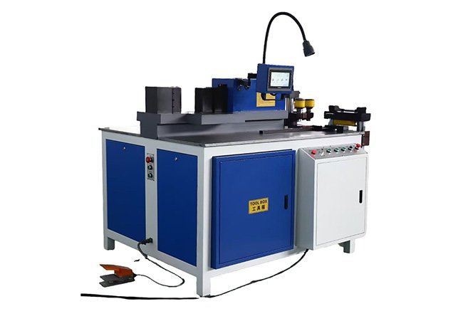
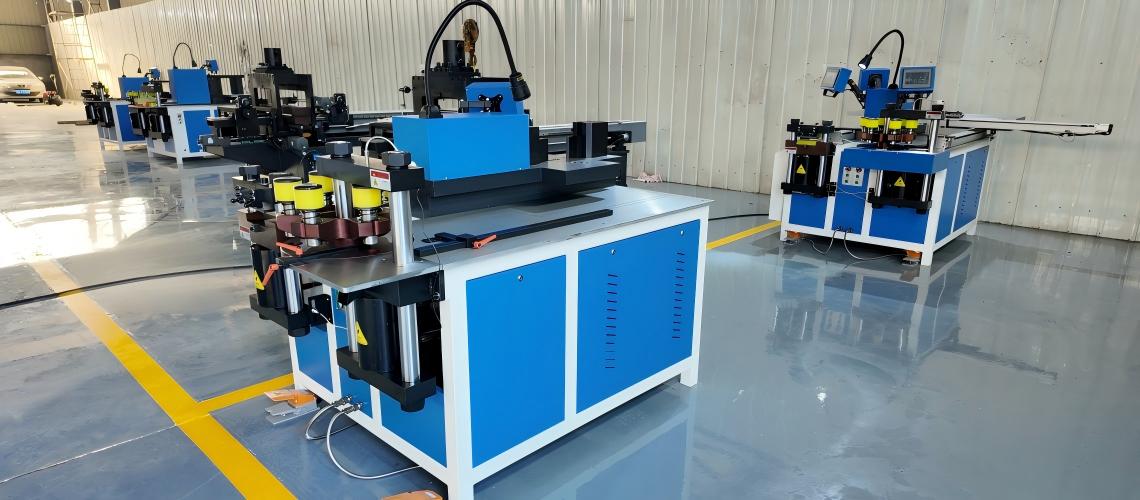
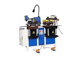
The GJBM803 is a manually fed hydraulic machine that integrates punching, shearing and flat bending in three dedicated processing stations. Its stated overall working range covers copper and aluminum busbars from 20–250 mm wide and 4–20 mm thick; actual capacity depends on the operation, material grade and tooling. A PLC touchscreen and CNC-assisted measuring system help operators establish repeatable processing positions while loading and longitudinal movement remain manual.
- Processes copper and aluminum busbars within a stated overall range of 20–250 mm in width and 4–20 mm in thickness
- Integrates punching, hydraulic shearing and flat bending in one machine frame
- Uses CNC-assisted measurement to reduce repeated tape measurement and manual marking
- Supports mixed-size parts, customized drawings and medium-batch production
- Uses dedicated processing stations powered by a shared 31.5 MPa hydraulic system
- DataSheet
- Punching
- Shearing
- Bending
| Item | Specification |
| Model | GJBM803 |
| Machine Type | Heavy-Duty Three-Station Hydraulic Busbar Processing Machine |
| Functions | Punching, Hydraulic Shearing and Flat Bending |
| Materials | Copper and Aluminum Busbars |
| Overall Width Range | 20–250 mm |
| Overall Thickness Range | 4–20 mm |
| Typical Workpiece Length | Up to 6,000 mm with suitable external support |
| Feeding | Manual |
| Measuring Method | CNC-Assisted Measurement |
| Controller | PLC with Touchscreen HMI |
| Hydraulic System | Shared Hydraulic System |
| Rated Hydraulic Pressure | 31.5 MPa |
| Total Installed Power | 15 kW |
| Power Supply | 380 V / 50 Hz / 3 Phase |
| Dimensions | 2,200 × 1,900 × 1,800 mm |
| Machine Weight | Approximately 3,200 kg |
| Item | Specification |
|---|---|
| Punching Force | 500 kN |
| Round-Hole Diameter Range | Ø4.3–Ø35 mm, subject to material thickness and selected tooling |
| Standard Hole Type | Round Holes |
| Optional Hole Types | Oblong or Customized Holes with Dedicated Punch-and-Die Tooling |
| Material Positioning | Manual Positioning with PLC-Assisted Digital Measurement |
| Punching System | Dedicated Hydraulic Punching Unit |
| Included Tooling | Standard Punch-and-Die Set Specified in the Confirmed Order |
| Item | Specification |
|---|---|
| Shearing Force | 500 kN |
| Shearing System | Dedicated Hydraulic Shearing Unit |
| Applicable Material | Copper and Aluminum Busbars |
| Material Positioning | Manual Positioning |
| Shearing Method | Hydraulic Shearing with Replaceable Blades |
| Shearing Capacity | Subject to Material Grade, Temper, Thickness and Blade Clearance |
| Workpiece Support | External Roller Support Recommended for Long Busbars |
| Item | Specification |
|---|---|
| Bending Force | 500 kN |
| Nominal Finished-Angle Range | 0–90° |
| Standard Bending Type | Flat Bending |
| Vertical Bending | Optional, Subject to Machine Structure and Dedicated Tooling |
| Material Positioning | Manual Positioning |
| Control Mode | PLC-Assisted Digital Measurement |
| Minimum Bending Radius | Subject to Material Thickness, Bend Geometry and Tooling |
| Hydraulic Pressure | 31.5 MPa |
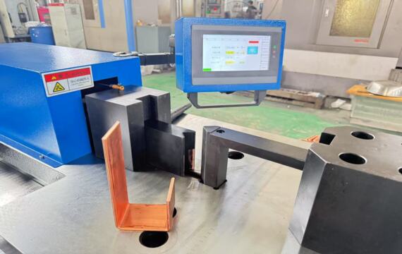
CNC-Assisted Measurement for Repeatable Positioning
Operators enter the required processing dimension through the control interface. The measuring system provides a positioning reference, after which the operator manually advances and aligns the busbar before activating the selected station. Loading and longitudinal feeding are not servo-controlled, allowing operators to handle different busbar lengths and customized parts.
Heavy-Duty Hydraulic Power for Thick Busbar Processing
A shared hydraulic system rated at 31.5 MPa powers the dedicated punching, shearing and bending stations. The complete machine weighs approximately 3,200 kg and uses a welded frame for high-load processing. Before shipment, each machine undergoes the checks defined in the factory inspection plan. Factory inspection records, including sample photos, processing videos and dimensional measurements, are available on request before shipment.
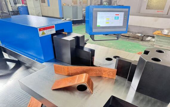
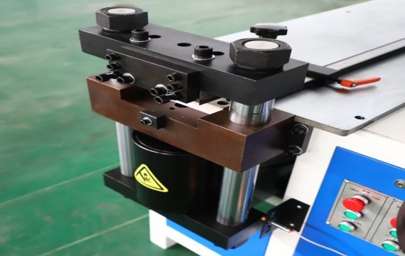
Three-Station Workflow and Workshop Requirements
The GJBM803 places the punching, shearing and bending stations within one machine frame. Operators manually move the busbar to the required station, reducing transfers between separate machines while retaining flexibility for customized parts.
When processing 6,000 mm busbars, use suitable roller supports and reserve sufficient loading and unloading clearance around the machine. The required workshop layout depends on the material length, operator position and production flow. A machine layout drawing is available for installation planning.
For long repetitive batches requiring automatic feeding, nesting or drawing-based processing, an automatic punching-and-shearing line is generally more suitable.
The stated overall range is 20–250 mm in width and 4–20 mm in thickness. This does not mean every 250 × 20 mm busbar can be processed with every hole size or bend geometry. Send the material grade, drawing, hole diameter, bend direction and bend radius for confirmation.
The GJBM803 processes copper and aluminum busbars. Actual capacity varies with material grade and temper. For copper or aluminum, provide the applicable material standard, grade or alloy, and temper so that the required punching force, shearing clearance and bending radius can be checked.
The CNC-assisted measuring system helps operators establish repeated punching, cutting and bending positions without marking every workpiece by hand. The busbar is still loaded and moved manually; the system should not be confused with an automatic servo feeding line.
Yes. Optional tooling can be designed for specified round or oblong holes, flat-bending geometries and other confirmed operations. Provide a dimensioned drawing, material grade, busbar thickness and required production quantity for tooling evaluation.
Please provide the material grade and temper, width and thickness range, maximum length, hole shapes and diameters, bend geometry and radius, expected monthly output, required voltage and frequency, destination country and dimensioned part drawings.

