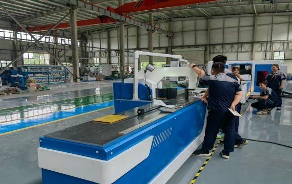
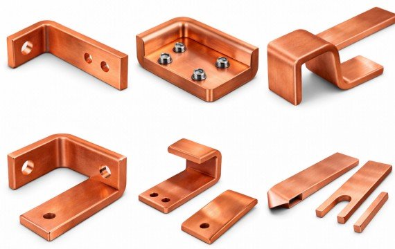
A CNC busbar machine improves manufacturing efficiency by reducing repeated measurements and positioning, shortening repeat-order setup times, and executing confirmed coordinates more consistently. The improvement should be measured through conforming parts, complete cycle time, changeover time, rework, and copper loss—not by punching speed or hydraulic stroke time alone. This guide explains how to establish a manual baseline and run a controlled comparison test during factory acceptance testing.
Quick Answer
CNC busbar machines create the greatest value when repeated measuring, positioning, data entry or model changeover limits production. Verify the benefit through minutes per conforming part, operator minutes per conforming part, first-pass yield, changeover time, rework and net copper loss.
How Should CNC Busbar Machine Efficiency Be Measured?
When selecting a CNC busbar processing machine, you should focus on the entire production process—from material loading to finished product inspection. Stages such as loading, measuring, positioning, processing, tool changing, inspection, correction, and unloading all impact production capacity.
Which Production Metrics Matter Most?
CNC efficiency should be evaluated by how many conforming parts are produced within a defined time, using a recorded number of operators and an agreed inspection standard. Production measurements include reducing positioning errors and shortening setup (changeover) times.
Evaluate CNC efficiency using conforming output, complete cycle time, operator labor, first-pass yield, rework rate, net copper loss and changeover time. Record all results under defined drawings, materials, tooling, operator and inspection conditions.
| Efficiency Metric | Calculation | What It Shows | Buyer Verification |
| Conforming Parts Per Shift | Total conforming parts completed during one defined shift | Actual production output under normal operating conditions | Record shift length, operator count, downtime and conforming quantity |
| Positioning Time | Measuring and positioning time ÷ processed parts | Time saved by CNC or servo positioning | Compare manual marking with automatic positioning using the same drawing |
| Repeat-Order Setup Time | Program selection to first conforming part | Efficiency of stored programs and repeat production | Include program recall, tooling setup, first-part correction and inspection |
| First-Pass Yield | First-pass conforming parts ÷ total processed parts × 100% | How many parts pass inspection without correction | Record conforming, reworked and scrapped parts separately |
| Rework Rate | Reworked parts ÷ total processed parts × 100% | Labor and inspection time lost to correction | Record correction time and type |
| Scrap Cost | Scrapped copper weight × material cost | Direct material loss caused by rejected parts | Use actual copper weight and current factory material cost |
| Material Utilization | Material used in conforming parts ÷ total input material × 100% | How efficiently raw copper is converted into conforming parts | Calculate by weight rather than part quantity |
Why Should You Establish A Manual Production Baseline?
Establish a manual or digitally assisted production baseline before estimating CNC savings. Without baseline data, you cannot determine whether the current bottleneck is marking, positioning, processing, tooling, inspection or material handling.
Where Does CNC Save Production Time?
Automatic positioning
Automatic positioning reduces repeated marking, ruler reading and mechanical-stop adjustment. The benefit is greatest when one part contains multiple hole or cutting coordinates. Only CNC-controlled axes should be included in the claimed time saving; manually positioned axes and secondary operations must remain in the complete cycle time.
Stored programs
Stored programs shorten repeat-order setup by recalling approved coordinates and process parameters. Program names should include the drawing number, revision and approval status. Obsolete programs should be locked or archived to prevent operators from recalling outdated dimensions.
Faster changeovers
CNC can shorten model changeovers when programs, tools and material are prepared in advance. Changeover time should be measured from the last conforming part of Model A to the first conforming part of Model B, including program selection, tooling, first-part correction and inspection.
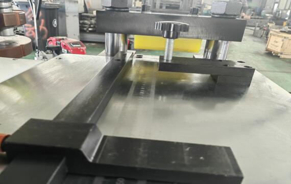
Data import
File import, geometry import, and automatic program generation are different functions. Confirm the supported formats, such as DXF, and whether imported geometry is used for complete program generation. Imported geometry should be checked against the approved drawing before being released to production.
Manual Vs CNC Busbar Production Test
A controlled production comparison provides more useful evidence than promotional cycle-time claims alone. The manual and CNC tests should use equivalent drawings, materials, tooling functions, inspection criteria and production boundaries.
How Should the Comparison Test Be Controlled?
To obtain accurate results, the CNC processing tests must be. The tests should utilize the same copper grade, material temper, busbar dimensions, processing drawings, tooling, and inspection standards.
Use trained operators for each production method and record the operator count, assigned tasks and total labor time. Do not force one operator to run an unfamiliar machine merely to make the test appear identical. Testing under identical conditions provides a true picture of the improvements a CNC busbar processing machine brings to your production. Record any differences in station layout, machine capacity, tooling, material handling, and operator tasks. Do not attribute every time difference to CNC control when the compared machines also differ in automation scope.
Which Test Data Should Be Published?
| Test Item | Manual Or Digital Positioning | CNC Or Servo Positioning | Buyer Record And Acceptance |
| Machine And Configuration | Record model, functions and positioning method | Record model, controlled axes and automation scope | Confirm machine model, tooling and software version |
| Controlled Test Workpiece | Same drawing, material grade, temper and dimensions | Same drawing, material grade, temper and dimensions | Record drawing number, revision, holes, bends and material certificate |
| Batch Size And Labor | Record all operators | Record all operators | Use the same inspection standard |
| First-Part Setup Time | Marking, stop adjustment, tooling and trial correction | Program recall, tooling and first-part correction | Measure from the start of program, tooling and material preparation to the completion and approval of the first conforming part. |
| Measurement And Positioning Time | Record manual measuring, marking and alignment time | Record servo feeding and positioning time | Calculate average positioning minutes per part |
| Processing Time | Record punching, shearing and bending time | Record punching, shearing and bending time | Separate processing time from positioning time |
| Tool Change Time | Record quantity and duration of tool changes | Record quantity and duration of tool changes | Use the same hole sizes, slots and bending tools |
| Material-Handling Time | Record loading, transfer and unloading time | Record loading, feeding and unloading time | Include assistants, roller support and manual secondary handling |
| Total Time for 10–20 Parts | Record continuous elapsed time | Record continuous elapsed time | Start at raw-material loading and finish after final inspection |
| Positioning Result | Measure target position against actual position | Measure target position against actual position | Record accuracy, repeatability and measurement method separately |
| Quality Result | Record conforming, reworked and scrapped parts | Record conforming, reworked and scrapped parts | Calculate first-pass yield, rework rate and scrap rate |
| Test Evidence | Measurement sheets, photos and continuous video | Measurement sheets, program revision and continuous video | Record test date, measuring tools and calibration status |
A 10–20-part test is a practical screening test for short-run consistency. It does not prove long-term process capability. Formal capability assessment requires an agreed sample size, tolerance, measurement system and acceptance method.
FengHua Published References
| FengHua Machine | Published Reference | Best-Fit Production | Required Test Verification |
| 303 Servo Positioning 3-in-1 Busbar Processing Machine | Integrates punching, shearing and bending for copper and aluminum busbars, with servo positioning for material feeding | Mixed-batch switchgear and control-panel production requiring three processes in one machine | Confirm which axes are servo-controlled; record positioning accuracy, repeatability, program recall time and complete cycle time |
| Fully Automatic CNC Busbar Punching And Shearing Production Line | Automatic feeding, CAD drawing import and published 0.2 mm accuracy | Repeated punching and fixed-length shearing for switchgear, transformer and power-distribution production | Verify positioning deviation, repeatability, feeding cycle, gripper dead zone, minimum finished length, file-import workflow and test method |
| High Precision CNC Servo Busbar Bending Machine For Copper & Aluminum Busbars | Published ±0.1° angle accuracy, flat and vertical bending, CAD drawing support and CE certification | Repeated flat bending and edge bending for switchgear, transformers and power-distribution busbars | Verify material grade, temper, thickness, tooling, bend radius, springback correction and angle variation across a test batch |
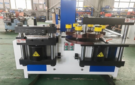
How Should Test Results Be Calculated?
| Efficiency Result | Calculation | What It Shows | Data Required |
| Time Saved | Manual minutes per conforming part − CNC minutes per conforming part | Actual time saved | Complete cycle time, conforming quantity and identical test conditions |
| Material-Loss Reduction | Manual scrap cost − CNC scrap cost | Direct copper-material savings from fewer rejected parts | Scrapped copper weight and actual material cost |
| Labor Cost Savings | (Manual hours − CNC labor hours) × hourly labor rate | Savings created by reduced measuring, positioning and correction work | Total operator hours and local labor rate |
| Estimated Payback Period | Incremental CNC investment ÷ estimated monthly operating savings | Approximate time required to recover the incremental installed investment. | Machine price difference, labor savings, material savings and avoided rework cost |
Use the same drawing, material, tooling, batch size, operator scope, and inspection standard. Payback results are planned estimates of returns.
Which Production Environments Benefit Most?
CNC creates the greatest value when the current bottleneck is measurement, positioning, program setup or model changeover.
| Application | Where CNC Saves Time | Metric To Record | Critical Limitation |
| Switchgear and control panels | Reuses breaker-hole coordinates, cabinet programs and confirmed bending positions across recurring models | Program-to-first-part time, hole-position variation and changeover time | Drawing revisions must be controlled, and hole positions should be verified during first-part inspection |
| Transformers and power distribution | Reduces repeated measurement and positioning on long, wide or heavy busbars | Positioning minutes per part, conforming parts and bend-angle variation | CNC control does not replace external material support, suitable tooling or operation-specific capacity verification |
| Energy storage systems | Speeds processing of compact parts with dense holes and related product variants | First-pass yield, positioning time and setup time between related programs | Clamp reach, feeding dead zones, minimum edge distance and near-edge deformation must be reviewed |
| EV charging equipment | Shortens changeovers between similar parts with frequent dimensional changes | Last-conforming-part to first-conforming-part time, rework rate and conforming output per shift | Correct program selection, revision control and access to matching dies are essential. |
CNC provides the greatest efficiency gain when your production contains repeated coordinates, recurring drawings, or frequent model changes. The result should be verified through complete cycle time and conforming output rather than positioning speed alone.
How Should CNC Efficiency Be Verified During FAT?
Factory acceptance testing should verify both dimensional results and the time required to produce conforming parts. The buyer and supplier should agree on the test workpieces, measurement method and acceptance criteria before testing begins.
| FAT Item | What To Measure / Test Method | Agreed Acceptance Criterion | Actual Result |
| Test Conditions | Record machine model, drawing number and revision, material grade, temper, busbar size, tooling, operator count and batch size | Must match the approved FAT test plan | Record |
| Measurement System | Record measuring-tool type, resolution and calibration status | Measuring equipment valid and suitable | Pass / Fail |
| Positioning | Compare commanded position with the measured hole or cutting position across repeated moves | Buyer drawing tolerance or agreed machine specification; 0.2 mm may be used only for the applicable FengHua automatic CNC punching and shearing line | Record deviation in mm |
| Punching Position | Measure hole-center position, center-to-center pitch and hole-to-edge distance | Within approved drawing tolerances | Record maximum deviation |
| Hole Diameter | Measure the finished hole in at least two directions | Within drawing diameter tolerance; no unacceptable ovality or deformation | Record minimum / maximum |
| Burr And Surface | Measure maximum burr height and inspect scratches, edge collapse and coating damage | Buyer-approved burr limit or approved reference sample | Record maximum burr height |
| Shearing | Measure finished length, squareness, cut-face quality and visible deformation | Within drawing length tolerance and approved edge-quality sample | Record dimensional deviation and Pass / Fail |
| Bending | Measure the released finished angle, bend-line position and inner radius | Drawing tolerance; ±0.1° may be referenced only for the applicable FengHua CNC servo bending machine under agreed material and tooling conditions | Record actual angle |
| Repeatability | Measure the same specified feature on the first, middle and final conforming parts of the test batch. | Maximum variation within the agreed repeatability limit | Record range or maximum variation |
| Changeover | Time from the last conforming part of Model A to the first conforming part of Model B | Within the agreed time, including program selection, tooling, loading, correction and inspection | Record minutes |
| Program Control | Test program creation, save, recall, editing, revision identification, backup and restoration | All agreed functions operate correctly, and obsolete or incorrect programs are clearly identified, restricted or rejected according to the approved workflow. | Pass / Fail |
| Safety Functions | Test guards, emergency stops, interlocks, alarms and restart behavior | All safety functions operate according to the approved safety checklist | Pass / Fail |
| Batch Output | Agreed batch continuously and record total elapsed time | At least the agreed number of conforming parts within the specified test time | Record conforming / reworked / scrapped parts |
| Test Evidence | Provide measurement sheets, program version, photos and continuous test video | Complete records signed or approved by both parties | Pass / Fail |
Published machine accuracy is not automatically the finished-part tolerance. FAT acceptance criteria should be agreed according to the selected machine, buyer drawings, material condition, tooling and measurement method.
Frequently Asked Questions
Which CNC Feature Usually Saves the Most Time?
The largest saving depends on the existing bottleneck. Automatic positioning is often most valuable when parts contain many coordinates, while program recall matters more for recurring orders. In mixed production, tooling preparation and changeover time may have a greater impact than hydraulic cycle speed.
Does CNC Automatically Reduce Scrap?
No. CNC can reduce variation caused by repeated manual measurement and inconsistent positioning, but it cannot correct an incorrect drawing, unsuitable tooling, material variation or an unapproved program. Compare conforming, reworked, and scrapped parts under equivalent production conditions.
Is a CNC Busbar Machine Efficient for Small-Batch Production?
A CNC machine can improve small-batch efficiency when parts contain several coordinates, drawings repeat, or model changeovers occur frequently. It may provide less benefit if programming, tooling, and first-part setup take longer than manual production. Compare complete minutes per conforming part rather than batch size alone.
Can CNC Efficiency Fall as Tooling and Materials Change?
Yes. Worn tooling can increase burrs, correction work and inspection time even when machine positioning remains stable. A new material batch may also change punching load, cutting quality or bending springback. Repeat first-part approval whenever material grade, temper, thickness, tooling, or clamping changes.
How Should Buyers Estimate CNC Payback Before Purchase?
Use the buyer’s current marking time, operator count, changeover time, rework rate, and net copper scrap loss. State the assumed machine utilization, working days per month, and copper recovery value. Run a representative comparison test using the buyer’s drawing and material, then calculate monthly labor savings, additional conforming output and avoided rework. Include tooling, software, installation, training and maintenance differences. Report the result as an estimated payback range and state every assumption. Do not present the estimate as a guaranteed return.
Final Thoughts
The value of a CNC busbar machine should be evaluated through complete cycle time, conforming output, changeover time, rework and net copper loss—not positioning speed alone.
Submit three drawings to FengHua: one common part, one high-volume part and one complex part. Include the material grade, batch size, current operator count, marking time, changeover time and conforming output. Our engineering team will prepare a manual-versus-CNC comparison plan covering positioning, complete cycle time, tooling, labor use and FAT measurements.