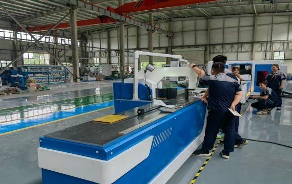
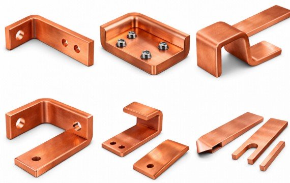
To choose a copper busbar machine, provide your actual drawings, copper grade and temper, maximum width and thickness, raw bar length, and required punching, shearing and bending operations.
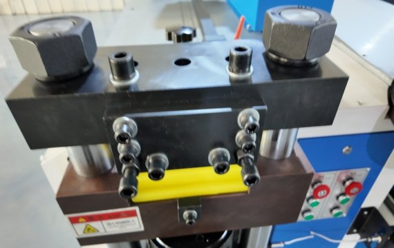
Quick Answer
Your machine selection should be based on drawing tolerances, production mix, operator availability and the required number of conforming parts per shift. Verify operation-specific capacity, controlled axes, tooling, complete cycle time, material-handling limits, floor-space requirements, technical support, total cost of ownership and factory acceptance test evidence.
| Production requirement | Typical starting configuration | Critical verification |
| Flexible low-volume orders and limited floor space | Hydraulic 3-in-1 machine | Operation-specific capacity, positioning time and station independence |
| Repeated models with frequent changeovers | Servo-positioning 3-in-1 machine | Controlled axes, program recall and changeover time |
| Repeated punching and fixed-length shearing | Automatic CNC punching and shearing line | Gripper dead zone, minimum raw and finished lengths, and conforming output |
| Complex bending | Dedicated programmable busbar bending machine | Controlled variables, tooling clearance, springback compensation and variation across repeated parts |
What drawings and production data should you prepare?
Start with one common part, one high-volume part and one complex part. If maximum width, thickness, raw-bar length, hole diameter or edge-bending requirements occur on different parts, include the relevant drawing for each limit.
Each drawing should identify the drawing number, revision, material grade and temper, dimensions, tolerances, hole positions, bend lines and surface requirements.
Also provide the average batch quantity, number of drawings processed per shift, operator count, current setup time, required conforming output per shift and expected future size range.
Which copper busbar machine configuration fits your production?
Hydraulic describes the drive or force-generation system. 3-in-1 describes integrated punching, shearing and bending functions. CNC and servo positioning describe control and positioning capabilities, while automatic describes the level of material handling.
When should you choose a hydraulic 3-in-1 machine?
A hydraulic 3-in-1 copper busbar processing machine combines punching, shearing, and bending on a single platform. Compared with three separate machines, it may reduce the required floor space and shorten the distance operators move busbars between operations.
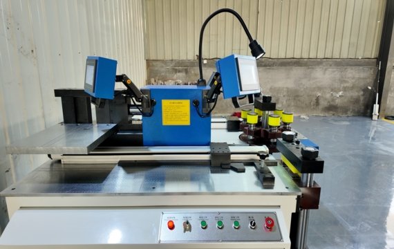
Depending on the approved configuration, material feeding, positioning and backgauge adjustment may still require manual operation.
Confirm whether the punching, shearing and bending stations share one hydraulic power unit, whether simultaneous operation is permitted and whether concurrent use affects pressure, cycle stability or hydraulic-oil temperature.
When should you choose a servo-positioning 3-in-1 machine?
For products requiring multiple processing positions, you might consider a servo-positioning copper busbar machine. A servo-positioning system may reduce manual marking, repeated dimensional checks and backgauge adjustment by moving a controlled positioning axis to programmed coordinates.
Note that some machines merely display dimensions and manual material positioning. Before purchasing, confirm which axes are automatically positioned, their travel range and feedback method, the available program-storage capacity, and which operations still require manual positioning. Do not assume that every value displayed on the controller represents an automatically controlled axis.
When should you choose dedicated CNC equipment?
A dedicated automatic CNC punching and shearing line becomes more valuable when repeated hole patterns and fixed cutting lengths account for most of the production workload. A dedicated programmable bending machine may be appropriate when bends are the main bottleneck.
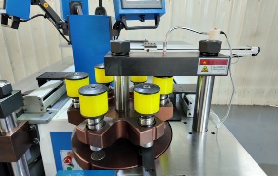
Separate machines can be used when staffing, material flow, and inspection capacity are available. Before selecting an automatic line, verify feeding travel, gripper dead zones, minimum raw-material and finished-part lengths, remnant handling, tooling changes and the unloading method.
For a programmable bending machine, confirm whether the controller manages bending stroke, finished-angle correction, material position or a combination of these variables. The term “programmable” does not prove that material feeding, tooling setup and every bending step are automatically controlled.
How should operation-specific capacity be verified?
A published maximum width × thickness does not prove that punching, shearing, flat bending and edge bending can all process that maximum material size. Ask the supplier to confirm each operation separately according to material grade, temper, dimensions, tooling, and drawing geometry.
How do hole layout and tooling reach affect selection?
Maximum punching diameter is only one selection factor. Verify hole pitch, hole-to-edge distance, slot dimensions, throat depth, clamp clearance, punch reach and gripper dead zones. A machine may have sufficient force but still be unable to reach the required feature.
How do bends affect tooling and machine clearance?
Flat bends, edge bends, offsets, U-bends and Z-bends require different tooling and clearance. A previously formed section may collide with the frame or tooling during the next bend. Review the bend direction, inner radius, bend-to-hole distance and spacing between adjacent bends using the actual drawing.
What tooling, software, documentation and support should be included?
| Item | Buyer verification |
| Tooling | Included sizes, quantities, compatible material and thickness range, custom dies, regrinding or replacement information and lead time |
| Software | Supported file formats, viewing and import capabilities, program-generation workflow, license period, user access, update policy and backup method |
| Documentation | English operating, safety and maintenance manuals, electrical diagrams, terminal layouts and hydraulic schematics |
| CNC recovery | Baseline program files, parameter backups, backup procedure and restoration instructions |
| Support | Service language, remote diagnostics, response process, warranty coverage and exclusions |
| Spare parts | Brands, model numbers, installed quantities, recommended stock quantities and approved local equivalents |
File viewing, geometry import, operation editing and complete machine-program generation are different functions. Ask the supplier to demonstrate the complete workflow from your drawing file to an executable machine program, including any manual editing required.
How should production mix, output and floor space affect your choice?
Factory size alone should not determine configuration. A large factory may process customized low-volume orders, while a small factory may repeatedly manufacture one standard part.
The more relevant decision factors are drawing variety, batch size, output target, operator count, changeover time and the available infeed, outfeed and maintenance space.
What fits flexible low-volume production?
For orders involving diverse dimensions, varying hole patterns, and adjustments to bending structures, equipment changeover efficiency is more critical than automatic feeding capabilities.
A hydraulic or servo-positioning 3-in-1 machine may be suitable. Manual or digitally assisted positioning may be sufficient for highly variable one-off parts, while servo positioning becomes more valuable when parts contain multiple coordinates, drawings recur, or model changeovers are frequent.
What fits repeated medium-batch production?
Repeated medium batches benefit from program storage, approved coordinates and prepared tooling. Without program storage and recall, operators must repeatedly re-enter dimensions and recreate positioning sequences, increasing setup time and the risk of using incorrect values.
Programs should be identified by drawing number, revision and approval status. Obsolete programs should be locked or archived to prevent outdated dimensions from being recalled during production.
What fits stable high-volume production?
Stable drawings, repeated hole patterns and standardized raw-material formats may justify automatic feeding and dedicated processing stations. This configuration can reduce repeated manual positioning, although unloading, sorting, inspection, program selection and tooling changes may still limit total line output.
Do not compare machines only by theoretical strokes per minute. Loading, positioning, tooling changes, first-part correction, inspection, unloading and sorting all affect complete cycle time and conforming output. Compare conforming parts and complete cycle time rather than theoretical strokes. Include material loading, positioning, processing, tooling changes, inspection, unloading, and first-part correction.
| Efficiency feature | Potential production value | Buyer verification |
| Automatic positioning | May reduce measuring, marking and alignment time | Measure positioning time |
| Stored and approved programs | May shorten repeat-order setup | Measure program-to-first-conforming-part time |
| Faster changeover | May reduce model-change downtime | Measure Model A last-conforming to Model B first-conforming time |
| Repeatable process settings | May reduce operator-dependent variation | Compare first-pass yield and variation |
Which configuration fits common busbar applications?
| Application | Typical challenge | Starting configuration | Critical check |
| Switchgear and control panels | Repeated breaker holes and cabinet variants | Servo-positioning 3-in-1 for mixed models; automatic CNC line for stable punching/shearing batches | Program revision, hole position and changeover time |
| Transformers and power distribution | Wide, thick and long busbars | Heavy-duty machine with external roller support | Operation-specific capacity and maximum-size sample |
| Energy storage and EV charging | Dense holes and compact bends | CNC positioning with application-specific tooling | Clamp reach, edge distance and bend interference |
| Custom busbar fabrication | High drawing variety | Flexible hydraulic or servo-positioning 3-in-1 machine | Setup time, tooling flexibility and first-part time |
What accuracy and finished-part requirements should be confirmed?
Machine positioning is only one part of the complete process. Finished-part accuracy is also affected by tooling condition, material properties, clamping, alignment, process settings and inspection methods. Overlooking these factors leads to hole position deviations and rework.
How are positioning accuracy, repeatability and resolution different?
Positioning accuracy is the deviation between the commanded position and the actual position reached by the controlled axis under a defined test method.
Machine repeatability is the variation when the same controlled movement returns to the same target repeatedly under equivalent conditions.
Controller resolution is the smallest increment the system can command or display. It should not be presented as positioning accuracy or finished-part accuracy.
Finished-part quality depends on the combined effects of machine positioning, tooling condition, material properties, clamping, alignment and process settings.
How should punching, shearing and bending be inspected?
When evaluating a copper busbar machine, acceptance should be based on measured finished parts rather than controller values or catalog claims alone.
For punching, record hole position, finished diameter, center-to-center pitch, hole-to-edge distance, ovality and maximum burr height.
For shearing, inspect finished length, cut squareness, cut-face quality and visible deformation.
For bending, measure the angle released from the tooling. Record the released bend angle, bend-line position, inside bend radius, flange dimensions, overall dimensions, twist, surface condition and variation across repeated parts.
What should an accuracy report include?
Require the supplier to record commanded and measured machine-axis positions separately from finished-part inspection results.
The machine’s claimed processing accuracy should be verified during a witnessed factory test using the buyer’s material, tooling, feature dimensions and inspection method. When installation or local production conditions differ from FAT, the relevant results should be checked again during site acceptance. A short-run test can verify basic processing capability, but it cannot by itself prove long-term reliability, tooling life or sustained process capability. These require longer production evidence, maintenance records or an agreed extended test.
What workshop, utility and safety requirements should be checked?
Calculate the complete operating envelope from the longest raw bar and finished part, not from the machine footprint alone. Include infeed and outfeed space, roller supports, operator movement, tooling storage, electrical-cabinet access and hydraulic-maintenance clearance.
Before quotation approval, confirm factory voltage, frequency, phase, allowable voltage variation, grounding system, installed power, hydraulic-oil requirements, cooling conditions and compressed-air demand where applicable.
Safety verification should cover guards, emergency stops, foot-switch protection, interlocks, overload protection, alarms, and restart behavior. The delivered machine, safety documents and destination-market compliance records should all refer to the same model and approved configuration.
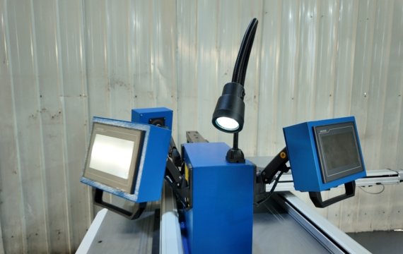
How should total cost of ownership be compared?
Compare the delivered-and-installed cost rather than the quoted machine price alone. Include standard and custom tooling, software licenses, packing, freight, insurance, duties, unloading, installation, commissioning, training, scheduled maintenance, spare parts, energy use and expected downtime.
Estimated Payback Period = Incremental Delivered-and-Installed Investment ÷ Net Monthly Operating Savings
Net Monthly Operating Savings = Labor Savings + Net Material-Loss Reduction + Avoided Rework Cost − Additional Software, Energy And Maintenance Costs
Net Copper-Loss Reduction = Avoided Scrap Weight × (Copper Purchase Price per Kilogram − Recoverable Scrap Value per Kilogram)
Additional output should be counted as a financial benefit only when the factory can sell that output or when the machine removes a verified production bottleneck.
What should be confirmed during factory acceptance testing?
Each factory acceptance test item should include the measurement method, agreed acceptance criterion and actual result.
| FAT item | Measurement method | Acceptance criterion | Actual result |
| Test conditions | Record model, drawing revision, material, dimensions, tooling, batch and operators | Match approved FAT plan | Recorded |
| Measurement system | Record instrument, resolution and calibration | Specified tolerance | Pass/fail |
| Positioning | Compare commanded and measured controlled-axis positions | Agreed positioning criterion | Deviation in mm |
| Machine repeatability | Repeat controlled movement to the same target | Agreed repeatability criterion | Maximum variation |
| Punching | Position, diameter, pitch and burr height | Drawing tolerance | Actual values |
| Shearing | Length, squareness and deformation | Drawing or approved sample | Actual values |
| Bending | Released angle, bend-line position and inner radius | Drawing tolerance | Actual values |
| Batch consistency | First, middle and final finished parts | Drawing or batch-variation limit | Recorded range |
| Changeover | Time from the last conforming part of Model A to the first conforming part of Model B, including program selection, tooling, material loading, first-part correction and inspection | Agreed complete changeover time | Minutes |
| Program control | Save, recall, edit, backup and restore | Pass/fail | Result |
| Safety | Guards, emergency stops, foot-switch protection, interlocks, alarms and restart behavior | Approved checklist | Result |
| Batch output | Total time, conforming, reworked and scrapped parts | Agreed output and quality result | Actual values |
Frequently Asked Questions
Why Can a Machine Perform Differently After Passing FAT?
A machine may pass FAT but perform differently after installation because of transport damage, incorrect leveling, unstable power, different material batches, inadequate roller support, incorrect tooling installation or changed process settings.
Site acceptance and commissioning should verify electrical supply, machine leveling, tooling installation, hydraulic settings, local material and first-part results against the approved FAT baseline.
How Should a Buyer Verify a Special Hole, Slot or Bend?
Do not rely on a photo alone to confirm that a machine can process a special feature. Special hole structural features may be constrained by dimensions or available machining space. Request a drawing that identifies the material, thickness, tolerances, hole or slot dimensions, bend radius, and surrounding geometry. The manufacturer should review tooling, throat or clamp reach, frame clearance, interference, and sample-test requirements before confirming capability or issuing a quotation.
Which first-year spare parts should importers keep locally?
Prioritize first-year spare parts by failure likelihood, downtime impact, local availability and international replenishment lead time. Depending on the machine configuration, typical items may include hydraulic seals, filters, sensors, relays, switches, cutting blades and frequently used punches and dies. The supplier should provide component brands, model numbers, installed quantities, recommended stock quantities and approved local equivalents.
Can one machine process both copper and aluminum busbars?
Many busbar machines can process both copper and aluminum, but the same capacity limits, tooling clearances and process settings should not be assumed for both materials. Grade, temper, thickness, and surface condition can affect die clearance, cutting quality, bending springback, and surface marking. Confirm operation-specific limits, retain separate approved samples, and process settings where required.
Final Thoughts
Submit one common drawing, one high-volume drawing, and one complex drawing to FengHua. Provide the material grade and temper, dimensional range, required operations, tolerances, required conforming output per shift, operator count, destination country, and factory power supply.
FengHua will prepare a written review covering the recommended machine configuration, operation-specific capacity, standard and custom tooling, positioning method, interference risks, material-handling limitations, unsupported features and proposed FAT items.