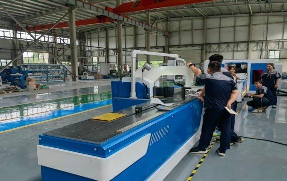
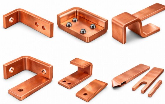
Busbar processing machines can punch, shear, and bend copper or aluminum busbars. Selection depends on whether the punching, shearing, and bending capabilities match your busbar, and actual production explains the machine’s core functions, which production benefits are realistic, and what evidence should be requested before purchase.
Quick Answer
A busbar processing machine performs punching, shearing and bending operations on copper or aluminum busbars. An integrated 3-in-1 machine places these stations on one platform, while dedicated machines allow the operations to run separately. CNC or servo control becomes valuable only when the controlled axis corresponds to the required position or machine movement. Depending on the configuration, the controlled variable may be punching position, cutting length, backgauge position, material-feeding position, bending stroke or angle correction.
Do not rely on maximum width, thickness, force, or controller resolution alone. Verify each required operation using your actual material, drawings, tooling, and agreed finished-part criteria.
| Machine function | Potential production value | What the buyer should verify |
| Punching | Produces drawing-defined round holes, slots and application-specific features | Hole geometry, tooling, feature reach, positioning and finished-hole quality |
| Shearing | Produces intermediate or finished busbar lengths | Operation-specific capacity, positioning, material support, squareness and cut quality |
| Bending | Produces drawing-defined installation geometry | Bend direction, radius, minimum leg, tooling access, springback and interference |
| Programmed positioning | Controls defined coordinates or machine movements where included | Controlled axes, usable travel, feedback method, programs and remaining manual tasks |
| Integrated processing | Places several processing stations on one platform | Station arrangement, power-unit configuration, workpiece movement and operator involvement |
A potential benefit should not be treated as a guaranteed production result until it has been reviewed against the actual machine configuration and representative busbar parts.
What Are The Core Functions Of A Busbar Processing Machine?
Busbar processing machines primarily perform three tasks: punching, shearing, and bending. Each function supports your copper or aluminum busbar drawings.
Busbar Punching
Punching is used to produce round holes, mounting holes, slots and other tooling-dependent features. For every representative part, identify the hole or slot dimensions, center-to-center pitch, hole-to-edge distance, busbar width and thickness, material condition and finished tolerance.
Rated punching force and maximum hole diameter do not prove that every required feature is reachable. Verify throat depth, tooling clearance, stripper access, clamp or gripper dead zones and usable positioning travel.
The sample test should measure finished hole position, diameter, pitch, edge distance, ovality, edge deformation and maximum burr height.
Busbar Shearing
Shearing cuts copper or aluminum busbars to an intermediate or finished length. Confirm the material grade and temper, width × thickness combination, regular and minimum finished lengths, positioning method and required cut quality. Infeed and outfeed supports are important for heavy busbars. Inadequate manual handling, alignment time, and operator-dependent variation.
Finished-part inspection should cover length, cut squareness, maximum burr, cut-face condition and visible deformation. If the sheared end will be used as a reference for a later operation, that requirement should be included in the acceptance criteria.
Busbar Bending
Bending produces flatwise bends, edgewise bends, offsets, U-bends, Z-bends and other drawing-specific geometries. Confirm the material grade and temper, width and thickness, bend direction, inner radius, minimum leg length, bend-to-hole distance, spacing between adjacent bends and the geometry of previously formed sections.
A machine may have sufficient bending force but still be unable to complete a complex part because the workpiece collides with the tooling, frame or worktable. Complex parts should therefore be reviewed through a tooling and interference drawing.
Because material condition and tooling affect springback, measure the finished angle after the busbar has been released from the tooling. Also record the bend-line position, leg dimensions, inner radius, twist and visible surface marks.
Which Busbar Machine Benefits Are Realistic?
A machine configuration may reduce material transfer, manual measurement, repeat-order setup or operator-dependent positioning. The actual benefit depends on the workpiece route, controlled axes, tooling, operator count and production mix.
Reduce Material Transfer
An integrated 3-in-1 machine may allow operators to move busbars between separate punching, shearing and bending areas.
Integration does not eliminate all manual handling. Long or heavy busbars require feeding, rotation, repositioning, support and removal. Compare the actual workpiece route rather than relying on the 3-in-1 label alone.
Reduce Manual Measurement and Positioning
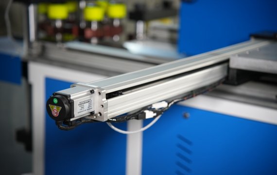
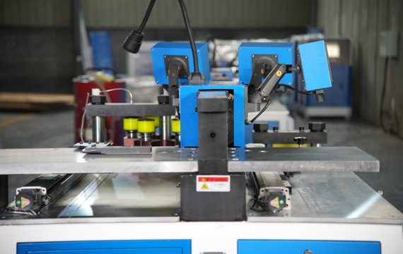
Programmed positioning may reduce repeated marking, ruler measurement and mechanical-stop adjustment when the relevant coordinate is controlled by the machine.
Ask the supplier to identify every controlled axis, usable travel, feedback method and operation that remains manual. A numerical display or CNC controller does not prove automatic material positioning.
Shorten Repeat-Order Setup
Stored and approved programs may shorten setup when the same drawing returns. Programs should be identified by drawing number, revision and approval status.
Measure the time from program selection to the first conforming part. Program recall alone does not include tooling changes, material loading, first-part correction and inspection.
Measure Complete Production Value
Measure setup performance and recurring production performance separately. Compare machine configurations under equivalent material, drawing, tooling, and operator conditions.
| Production Metric | How to | It Shows |
| Setup-to-First-Conforming-Part Time | Program and tooling setup + material loading + positioning + processing + first-part correction + inspection | How quickly conforming production |
| Recurring Complete Cycle Time | Loading + positioning + processing + routine inspection + unloading | Stable time after setup |
| Changeover Time | Time from the last conforming part of Model A to the first conforming part of Model B | Downtime required to change drawings, programs, tooling and material |
| Conforming Parts p | Conforming parts ÷ total assigned operator hours | Usable output relative to direct labor input |
| First-Pass Yield | Conforming parts without correction ÷ total processed parts × 100% | Process produces acceptable parts without rework |
| Scrap Rate | Rejected material weight ÷ total material input weight × 100% | Material loss under the recorded production conditions |
Total assigned operator hours equal elapsed production, the number of operators directly assigned to reworked and rejected and configurations.
How Should Buyers Verify Claimed Busbar Machine Benefits?
High precision, high productivity, low labor costs, and low material waste should be considered results verification. Should correspond to the quoted machine configuration, material, tooling, operator scope, and defined test conditions.
| Claimed Benefit | Do Not Verify It By | Better Buyer Evidence |
| Higher Accuracy | Controller resolution or positioning value alone | Finished-part measurements against agreed drawing criteria |
| Higher Productivity | Stroke rate or isolated machine cycle alone | Complete cycle time and conforming output |
| Less Labor | “Automatic” in the machine name | Actual manual and breakdown |
| Less Material Handling | 3-in-1 label alone | Actual workpiece route and station transfer requirements |
| Better Consistency | One successful sample | Agreed short-batch results where repeatability needs verification |
| Lower Waste | Machine-precision claims alone | Material input, remnant, rework and rejected-part records |
Machine specifications and production results should be recorded separately. Rated force, axis accuracy, controller resolution, and nominal cycle speed describe parts of the machine configuration. Finished-part accuracy, conforming output, labor requirement, and material loss are production results that must be measured under defined test conditions. Comparing suppliers using different controller parameters, automation specifications, or testing methods.
How Should a Busbar Processing Machine Be Tested Before Purchase?
Please submit one common part, one maximum required capacity, and one complex part. If the maximum punching, shearing, flatwise bending, and edgewise bending requirements appear on different drawings, include one representative drawing for each.
Buyer’s actual material or an agreed equivalent. Record the machine model, drawing revision, material, tooling, operator count, setup time, complete cycle time and finished-part measurements.
One successful sample does not demonstrate short-batch consistency or long-term process capability. Run an agreed short batch and measure final parts.
| Test item | What to record | Acceptance basis |
| Test conditions | Machine, drawing revision, material, tooling, batch and operators | Approved test plan |
| Punching | Hole position, diameter, pitch, edge distance and burr | Drawing tolerance |
| Shearing | Length, squareness, cut quality and deformation | Drawing or approved sample |
| Bending | Released angle, bend-line position, radius and leg dimensions | Drawing tolerance |
| Complex-part clearance | Complete agreed processing sequence | No interference or unsupported step |
| Program control | Save, recall, edit, backup and restore | Agreed machine scope |
| Batch consistency | First, middle and final finished parts | Drawing or batch-variation limit |
| Complete output | Total time, conforming, reworked and rejected parts | Agreed output and quality result |
The supplier should provide a written drawing-review conclusion, tooling list, measurement record, measuring-instrument information, test conditions and an unedited continuous-processing video.
Frequently Asked Questions
What Electrical and Utility Information Should an Importer Confirm?
Confirm the actual factory voltage, frequency, phase, allowable voltage variation and grounding system. Also verify installed power, control voltage, hydraulic-oil requirements, cooling conditions and compressed-air demand where applicable.
The approved quotation, machine nameplate, manuals and electrical drawings should show the same configuration.
What Spare Parts and Consumable Information Should an Importer Request?
The spare-parts list should correspond to the exact machine model and delivered configuration. Request part numbers, installed quantities, recommended stock quantities, replacement procedures, prices and replenishment lead times.
Typical items may include hydraulic seals, filters, sensors, relays, switches, cutting blades and frequently used punches and dies. Standard tooling, custom tooling and routine consumables should be listed separately.
What Technical Documents Should Be Delivered?
Technical delivery should include operating, safety and maintenance manuals, electrical diagrams, terminal layouts, hydraulic schematics, tooling lists, component lists and preventive-maintenance requirements.
CNC-controlled equipment should also include program backups, machine-parameter backups, software-license information and written backup and restoration instructions. Document language and file format should be agreed before shipment.
Can the Three Stations of a 3-in-1 Machine Operate at the Same Time?
It depends on the hydraulic and control configuration. Some machines use one shared hydraulic power unit, while others use independent systems. Confirm whether concurrent operation is permitted and whether simultaneous use affects pressure, cycle stability or hydraulic-oil temperature.
Does CNC Mean the Busbar Machine Is Fully Automatic?
No. CNC means that one or more machine variables are programmed and controlled. Material loading, positioning, tooling changes, bending, inspection, and unloading work. Ask the supplier to list every controlled axis and every remaining manual task.
Submit Your Busbar Drawings for a Machine Review
Choose a busbar processing machine by matching every required operation to your actual material, drawings, finished-part tolerances, production mix and required conforming output.
Submit one common drawing, one drawing representing the maximum required capacity and one complex drawing to FengHua. FengHua will prepare a written review covering the recommended machine configuration, operation-specific capacity, controlled axes, positioning method, standard and custom tooling, material-handling limitations, unsupported features and proposed sample-test items.