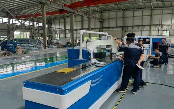
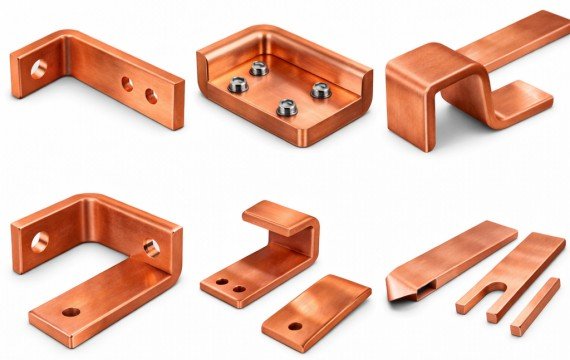
Buying a busbar machine should begin with representative drawings, material specifications and finished-part requirements—not with the machine’s maximum tonnage, catalog thickness or the word “CNC.” The selected configuration must support the required punching, shearing and bending operations, approved tooling, material handling, operator workflow, conforming output and acceptance test.
This guide explains how to prepare an RFQ, compare machine configurations, review supplier quotations and verify the proposed equipment through sample processing, FAT and site acceptance.
Quick Answer
Select a busbar machine from your drawings and complete production workflow. Confirm material grade and temper, common and maximum width × thickness, raw-bar length, hole and slot requirements, bend geometry, finished tolerances, batch mix, operator tasks and required conforming output.
Verify the capacity of punching, shearing and bending stations separately. Do not assume that maximum catalog width and thickness apply to every operation or can be combined under all tooling conditions. Compare the complete cycle, changeover, tooling, material handling, inspection, documentation, FAT and total project cost before approving a machine.
| Production Requirement | Starting Configuration | Critical Buyer Check |
|---|---|---|
| Mixed drawings and flexible batches | Hydraulic or 3-in-1 machine with manual or assisted positioning | Operation-specific capacity, tooling and positioning time |
| Punching, shearing and bending in limited floor space | 3-in-1 busbar processing machine | Capacity and independence of each station |
| Recurring coordinates and frequent model changes | CNC or servo-positioning configuration | Controlled axes, program recall and remaining manual tasks |
| Stable repeated punching and fixed-length shearing | Automatic punching and shearing line | Feeding, gripper dead zone, remnant handling and downstream bending |
| Complex or repeated bending | Dedicated programmable busbar bender | Tooling clearance, controlled variables and finished-part variation |
| Several operations must run in parallel | Separate dedicated machines | Staffing, transfer, WIP and line balance |
What Is a Busbar Machine?
A busbar machine is equipment used to punch, shear, bend or form copper and aluminum conductors according to approved production drawings.
The term may refer to a dedicated machine, a 3-in-1 platform, a CNC or servo-positioning machine, or an automatic punching and shearing line. These descriptions refer to different aspects of the equipment and are not mutually exclusive.
What Information Should You Prepare Before Requesting a Quotation?
| RFQ Information | What to Provide | Why It Matters |
|---|---|---|
| Representative Drawings | One common part, one high-volume part and one complex part | Prevents selection from one easy sample |
| Drawing Control | Number, revision and approval status | Prevents obsolete production data |
| Material | Copper grade or aluminum alloy, temper and batch requirements | Affects force, tooling, burr and springback |
| Common Section | Common width × thickness | Defines normal production workload |
| Maximum Section | Maximum width × thickness by actual part | Confirms peak operation requirements |
| Raw-Bar Length | Common and maximum supplied length | Affects loading, support and layout |
| Finished Length | Target range and tolerance | Affects shearing and positioning |
| Holes and Slots | Diameter, shape, pitch, edge distance and quantity | Defines tooling and positioning requirements |
| Bending | Direction, angle, radius, bend line and sequence | Defines bending station and tooling |
| Surface Requirements | Scratch, indentation, plating or coating limits | Affects tooling and handling |
| Production Mix | Part families, quantities and change frequency | Affects flexibility and automation value |
| Required Output | Conforming parts per shift or agreed period | Supports system-balance comparison |
| Labor | Available operators and assistants | Defines practical workflow |
| Factory Utilities | Voltage, frequency, air or hydraulic requirements | Defines electrical and installation scope |
| Workshop Layout | Infeed, outfeed, rotation, inspection and WIP space | Confirms physical installation |
| Inspection | Critical characteristics, tolerances and instruments | Defines acceptance method |
The approved electrical design should define the conductor material and section. Machine selection should verify whether the proposed equipment can process that material—not determine the electrical conductor size.
Can the Same Machine Process Copper and Aluminum?
Some busbar machines can process both materials, but buyers should not assume that identical tooling clearance, bend correction or operating parameters apply to every copper grade or aluminum alloy. Confirm the actual material, temper, width × thickness, surface condition, tooling and finished-part requirements through representative samples.
How Should Published Machine Capacity Be Interpreted?
| Published Item | What It Does Not Automatically Prove | Required Verification |
|---|---|---|
| Maximum Width | That every station accepts the same width | Confirm punching, shearing and bending separately |
| Maximum Thickness | That maximum width and thickness can always be combined | Test the actual width × thickness combination |
| Hydraulic Force | Finished-part accuracy or surface quality | Process the representative part |
| Punching Range | Every hole is reachable on every drawing | Check edge distance, throat and tooling reach |
| Bending Angle | Finished released-angle tolerance | Measure the released part |
| CNC Resolution | Axis accuracy or finished-part accuracy | Compare commanded, axis and finished-part results |
| Positioning Accuracy | Repeatability across batches or operators | Record first, middle and final parts |
| Machine Length | Support for the buyer’s raw bars | Confirm rollers, tables and rotation space |
| Automatic | Complete unattended production | Define loading, tool change, rotation, inspection and unloading |
| Production Speed | Conforming output per shift | Record the complete workflow |
Maximum catalog values should not be treated as one universal processing envelope. A machine may support one maximum width under one operation and another maximum thickness under different tooling conditions.
How Should Busbar Machine Terminology Be Interpreted?
| Term | What It Describes | What It Does Not Confirm |
|---|---|---|
| Hydraulic | How punching, shearing or bending force is generated | Positioning method or automation level |
| 3-in-1 | Integration of punching, shearing and bending stations | Automatic feeding or equal station capacity |
| CNC | Programmed control of defined machine variables | Fully automatic loading and inspection |
| Servo Positioning | Closed-loop movement of a defined positioning axis | Control of every station or finished dimension |
| Automatic Line | Agreed feeding, positioning and processing sequence | Zero manual tasks or simple changeovers |
| Dedicated Machine | One main operation such as punching or bending | Lower output or less accuracy |
| Separate Machines | Independent equipment for different operations | Poor stability or low efficiency |
Where Are Busbar Machines Used?
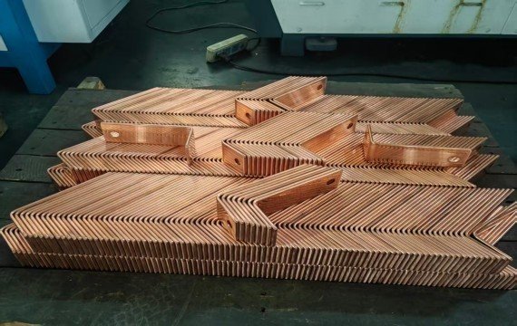
Busbar machines are used in switchgear, electrical panels, transformers, busduct systems, energy-storage equipment, EV charging equipment and other electrical assemblies. Final machine selection should be based on actual drawings and production requirements rather than the industry name alone.
Transformer Manufacturing
Transformer manufacturers use busbar processing machines to produce accurate conductive connections for power equipment.
How Should Tooling Be Compared?
Machine capacity alone does not confirm that the required holes, slots, bends or formed features can be produced.
| Tooling Item | What to Confirm |
|---|---|
| Standard Tooling | Exact tool codes, quantities and applications included in the quotation |
| Optional Tooling | Price, application and delivery time |
| Customized Tooling | Drawing review, design responsibility, approval and test method |
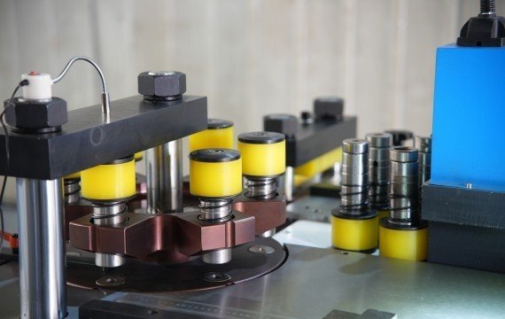
| Punching Tools | Hole or slot size, shape, material range and applicable thickness |
| Bending Tools | Flat bending, edge bending, offset bending and special forming |
| Tooling Clearance | Access to holes, bend lines and previously formed sections |
| Tool Change | Installation method and time from the last conforming Part A to the first conforming Part B |
| Maintenance | Sharpening, repair, inspection and replacement requirements |
| Spare Tooling | Recommended initial spare tools and replacement lead time |
Do not accept “tooling included” without an itemized list. A machine with sufficient nominal force may still be unsuitable when the required tooling cannot reach the drawing feature or when a formed section interferes with the tool or machine frame.
What Should Be Verified During FAT?
Factory acceptance testing should use agreed drawings, materials, tooling and inspection methods.
| FAT Item | What to Verify |
|---|---|
| Machine Identity | Model, serial number and approved configuration |
| Test Drawing | Drawing number, revision and critical characteristics |
| Test Material | Grade or alloy, temper, width × thickness and batch |
| Processing Functions | Punching, shearing and bending stations included in the approved scope |
| Tooling | Standard, optional and customized tool codes |
| Punching Results | Hole size, position, pitch, burr and deformation |
| Shearing Results | Finished length, squareness, burr and end deformation |
| Bending Results | Released angle, bend-line position, radius and overall dimensions |
| Program Control | Save, recall, edit, back up and restore |
| Operator Tasks | Loading, alignment, rotation, tool changes and inspection |
| Safety | Guards, emergency stops, interlocks and restart behavior |
| Documentation | Manuals, electrical drawings, parameters and backups |
| Spare Parts | Included items and identification |
| Open Issues | Deviations, corrective actions and approval status |
A short FAT can verify immediate machine performance under recorded conditions. It cannot by itself prove long-term reliability, tooling life or sustained production capability.
Frequently Asked Questions
What Factors Affect Busbar Machine Price?
Busbar machine price depends on the approved configuration, operation-specific capacity, positioning method, tooling, automation scope, electrical components, software, safety functions, documentation, training, spare parts and FAT requirements.
Compare the total project scope rather than the machine price alone.
Can a Busbar Machine Process Copper and Aluminum?
Some machines can process both materials.
Confirm the actual copper grade or aluminum alloy, temper, width × thickness, tooling, punching clearance, bend correction and finished-part requirements through representative samples.
What Is the Difference Between a Hydraulic and CNC Busbar Machine?
Hydraulic and CNC describe different aspects of the machine.
Hydraulic describes how punching, shearing or bending force is generated. CNC describes programmable control of defined machine variables.
One busbar machine may be both hydraulic and CNC-controlled.
What Thickness Can a Busbar Machine Process?
Maximum thickness depends on the material, width, operation, tooling and machine configuration.
Confirm punching, shearing and bending capacity separately. Do not assume that one general catalog thickness applies to every station.
What Information Should I Provide When Buying a Busbar Machine?
Provide representative drawings, material grade or alloy, temper, common and maximum width × thickness, raw-bar length, hole and slot requirements, bend geometry, tolerances, production mix, required output, workshop layout, utilities and FAT requirements.
Final Thoughts
A suitable Busbar Machine helps electrical manufacturers improve processing accuracy and production. Need help selecting the right busbar machine?Fenghua provides busbar cutting, punching, and bending solutions based on your busbar size, production requirements, and application needs