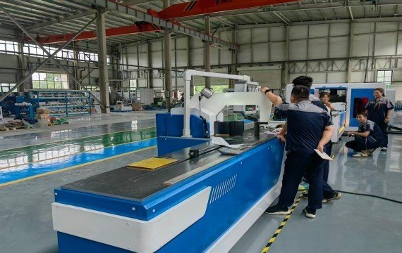
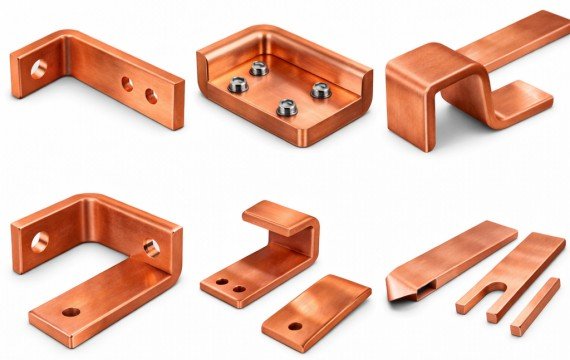
Choosing a busbar bending machine should begin with the buyer’s bend geometries, finished-part tolerances, batch structure and required conforming output. This guide compares three practical procurement configurations: a CNC hydraulic bender with manual or digital material positioning, a CNC bender with servo-controlled positioning, and a CAD/CAM-connected CNC bending system.
Quick Answer
A CNC hydraulic bending machine with manual or digital positioning may suit high-mix work when flexible tooling and lower investment are priorities.
A CNC busbar bending machine with servo-controlled positioning becomes more valuable when parts repeat, material positions can be programmed and model changeovers occur frequently.
A CAD/CAM-connected CNC system is useful for drawing-based program preparation, controlled revision exchange, or production-data integration. Connectivity does not automatically prove material handling bends.
Choose the configuration from your actual drawings, controlled-axis requirements, tooling, setup-to-first-conforming-part time, complete cycle time and FAT results.
How Should Industrial Buyers Compare the Three Configurations?
Industrial buyers should compare the three configurations using the same drawings, material conditions, tooling scope, batch size, operator requirements, and inspection method. For you, the equipment supports your actual production needs.
Part and Capacity Match
Confirm the material grade and temper, width × thickness combination, bend direction, inner radius, minimum leg length, bend-to-hole distance and previously formed geometry.
Published maximum width and maximum thickness should not be assumed to apply together in both flat and edge bending.
Control and Workflow Match
List every controlled axis and controlled variable. Confirm whether CNC controls bending stroke, angle correction, backgauge position, material position or only one of these functions.
Also record program-storage capacity, revision identification, remaining manual operations, tooling-change time and setup-to-first-conforming-part time.
Testing and Delivery Evidence
Use the buyer’s actual material or an agreed equivalent. The supplier should provide a written drawing review, tooling list, first-part measurement record, short-batch results, FAT record, program backups, manuals, training scope and after-sales terms.
A configuration should be recommended only after unsupported features, material-handling limitations and testing conditions have been stated clearly.
Top Three Busbar Bending Machine Configurations
The following three configurations represent practical procurement options for different production structures, positioning requirements, and software workflows. They are reference configurations for industry-standard machine categories. Product structures and production needs.
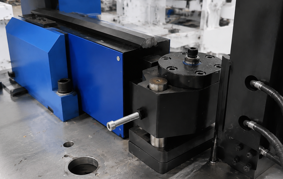
CNC Hydraulic Bending machine with Manual or Digital Positioning
A CNC hydraulic bending machine uses hydraulic force for the bending movement while CNC control may manage the ram stroke, angle correction or another defined machine variable.
Material positioning may remain manual or may use a digital backgauge, depending on the machine configuration.
This configuration can provide investment and tooling flexibility for high-mix production, but the buyer should not assume that CNC control includes automatic material positioning.
CNC Bending machine with Servo-Controlled Positioning
A CNC bending machine with servo-controlled positioning is useful when one or more material positions repeat across recurring parts.
The servo-controlled function may be a backgauge, material stop, or feeding-defined movement. Servo control should not be assumed to include automatic loading, bending-force control, or finished-angle measurement.
Program storage and approved positioning values can shorten repeat-order setup, but the supplier should demonstrate program creation, revision identification, recall, first-part correction and changeover between two actual products.
Ask the supplier to list every servo-controlled axis, travel range, positioning method, feedback device, accuracy test method, and operation that still.
CAD/CAM-Connected CNC Bending System
A CAD/CAM-connected CNC bending system may support drawing import, geometry transfer, editable operation generation, complete machine-program generation or production-data exchange. These functions are different and should be demonstrated separately.
Repeated data entry only when the file workflow, program revision, and machine interface operate correctly. It does not prove automatic material handling, springback correction, or complex parts.
Complex flat bends, edge bends, offsets, U-bends and Z-bends still depend on tooling, frame clearance, minimum leg length, bend-to-hole distance and the geometry of previously formed sections.
Before purchase, verify supported file formats, actual import workflow, software license, update policy, backup and restoration, interface or protocol, offline operation and the complete process from drawing selection to an inspected finished part.
How Do The Three Configurations Compare?
| Comparison | CNC hydraulic with manual/digital positioning | CNC with servo-controlled positioning | CAD/CAM-connected CNC system |
| Bending force | Normally hydraulic; confirm actual drive | Hydraulic or electromechanical, model dependent | Model dependent |
| Bending control | Stroke, ram position or correction function, model dependent | CNC control plus one or more servo-controlled axes | CNC control plus defined software/data workflow |
| Material positioning | Manual, digital stop or optional controlled axis | Servo-controlled selected axis | Manual, servo-controlled or automatic, model dependent |
| Program functions | Basic program storage or optional | Program storage, recall and revision control | Drawing import, operation generation or production-data exchange |
| Best production fit | High-mix and tooling | Recurring parts and frequent product changeovers | Factories requiring controlled digital program flow |
| Main limitation | Manual positioning and operator dependence may remain | Servo scope may be limited to one selected axis | Connectivity does not prove geometric capability or automatic handling |
| Main buyer check | Capacity, tooling and controlled variable | Servo-controlled axes, positioning results and changeover | File workflow, interfaces, backup and complete production cycle |
| Recommended FAT | Representative first-part test | Program recall and short-batch test | Drawing-to-finished-part workflow demonstration |
A more advanced controller does not automatically make a machine more suitable for your actual parts. The recommended configuration should be selected from your drawings, production structure, available operators and acceptance requirements.
Which Configuration Fits Your Industry?
Different electrical industries: busbar processing. Equipment selection should be based on your product structure, processing technology, and orders. Can reduce rework.
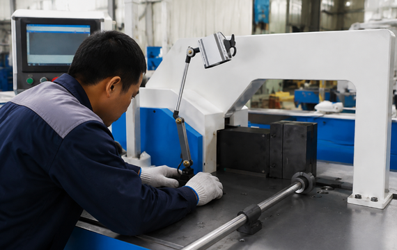
Switchgear And Electrical Panel Manufacturing
Switchgear and electrical-panel production often includes recurring busbar parts together with cabinet-specific variants.
A CNC bender with servo-controlled positioning may reduce repeated manual positioning when material locations repeat. A CAD/CAM-connected system may provide additional value when approved drawing data and program revisions are exchanged between engineering and production.
Measure program-to-first-conforming-part time and complete model-change time rather than assuming that program storage alone improves output.
Transformer And Busduct Production
Transformer and bus duct long, wide, or thick copper and aluminum busbars.
Confirm the actual width × thickness combination for flat and edge bending. Also review inner radius, material support, infeed and outfeed space, lifting requirements, operator count and maximum-size sample results.
Rated bending force alone does not prove that the machine geometry or material handling.
Energy Storage And EV Electrical Equipment
Energy-storage and EV electrical equipment may use compact busbars, coated or tinned surfaces and closely spaced bends or holes.
Machine bend-to-hole distance, minimum leg length, tooling access, clamp clearance, surface marking, and interference during the complete bend sequence.
A connected CNC system is valuable only when the buyer requires drawing-based program preparation, revision control or production-data exchange. Verify the complete digital workflow using an actual drawing before purchase.
What Should You Confirm Before Requesting A Quote?
To obtain an accurate quote, suppliers need to understand requirements. Preparing complete documentation in advance can reduce repeated communication and delivery failures from failing to meet production needs.
Quotation Information Checklist
| Information the buyer provides | Supplier must confirm | Why it matters |
| Material grade and temper | Supported material condition and test basis | Affects force, springback and cracking risk |
| Surface condition | Tooling contact and protection method | Tinned, coated or soft surfaces may mark |
| Regular and maximum width × thickness | Capacity for flat and edge bending separately | Maximum values may use different conditions |
| Raw-bar and finished-part length | Loading, support and removal method | Affects handling and workshop space |
| Bend direction and inner radius | Tooling and capacity | Different geometries require different tools |
| Minimum leg and bend-to-hole distance | Tooling access and deformation risk | Identifies unreachable or unstable features |
| U-, Z-, offset or torsion geometry | Frame and tooling interference | Force alone does not prove feasibility |
| Angle and linear tolerances | Measurement and acceptance method | Separates machine positioning from finished results |
| Average batch and drawings per shift | Recommended control and automation | Prevents over- or under-configuration |
| Operator count | Material-handling and labor requirement | Affects conforming output per labor hour |
| Required output | Complete-cycle test method | Avoids relying on nominal speed |
| Software requirements | File workflow, license and interface | Prevents misunderstanding of “CAD support” |
| Destination and factory power | Electrical and compliance configuration | Prevents installation incompatibility |
| Representative drawings | Written tooling and feasibility review | Identifies unsupported requirements |
How Should Importers Evaluate A Supplier?
Supplier evaluation should be based on documented evidence linked to the quoted machine model and delivered configuration. Request a written drawing review, approved technical proposal, tooling list, sample measurement records, FAT results, applicable compliance documents, software scope, training plan and written after-sales terms. General certificates or demonstrations from a different machine model should not be treated as evidence for the quoted configuration.
Supplier Evaluation And FAT Checklist
| Evaluation Item | Buyer Should Verify | Required Evidence |
| Supplier Identity | Manufacturer status and production scope | Legal and factory information |
| Engineering Review | Configuration linked to actual drawings | Written engineering conclusion |
| Machine Selection | Model and capacity linked to actual parts | Approved technical proposal |
| Tooling | Included, optional and customized dies | Tooling list and drawings |
| CNC Control | Controlled axes and remaining manual tasks | Configuration sheet and demonstration |
| First-Part Test | Angle, bend position and finished dimensions | Signed measurement record |
| Short-Batch Test | Variation under agreed conditions | Measurement report and video |
| Factory Acceptance Test | Machine, safety, tooling and documents | Signed FAT record |
| Training | Setup, operation and inspection | Training record |
| After-Sales | Parts and process | Written service scope |
| Software and data | File formats, import workflow, licenses, interfaces, backup and recovery | Live demonstration and written software scope |
| Installation conditions | Voltage, frequency, phase, grounding, footprint, infeed, outfeed and service access | Approved layout and utility sheet |
| Safety and compliance | Guards, emergency stops, interlocks, restart behavior and destination requirements | Signed checklist and applicable documents |
Frequently Asked Questions
Which Busbar Bending Machine Should an Importer Use as a Demonstration Model?
Choose a demonstration model, material sizes, bend geometries, and buyer budgets in the local market.
The machine should use flexible tooling, allow clear first-part measurement and support repeatable demonstrations without excessive setup. Do not select the highest-automation model unless local customers can verify and use the additional functions. The demonstration should include one common part, one maximum-size part and one complex part, together with measurement records and a tooling list.
What Costs Should Be Included Beyond the Machine Price?
Include standard and custom tooling, software licenses, packing, freight, insurance, duties, customs clearance, unloading, foundation work, installation, commissioning, training, spare parts, scheduled maintenance, energy use and expected downtime.
Compare delivered-and-installed cost and total cost of ownership rather than the quoted machine price alone.
What Warranty Terms Should Be Written into the Purchase Agreement?
The agreement should define the warranty period, covered components, consumables and exclusions, troubleshooting process, remote-support method, response time, replacement-parts responsibility, international freight responsibility and conditions for on-site service.
It should also state which party pays for technician travel, accommodation, customs charges and replacement-part delivery when an overseas service visit is required.
Submit Your Drawings for a Configuration Review
On the buyer’s actual parts, controlled-axis requirements, tooling, program workflow, production structure, and acceptance criteria. FengHua will prepare a written review covering the recommended configuration, flat- and edge-bending capacity, controlled axes, material-positioning method, standard and custom tooling, software workflow, interference risks, unsupported features and proposed FAT items.