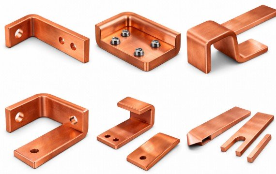
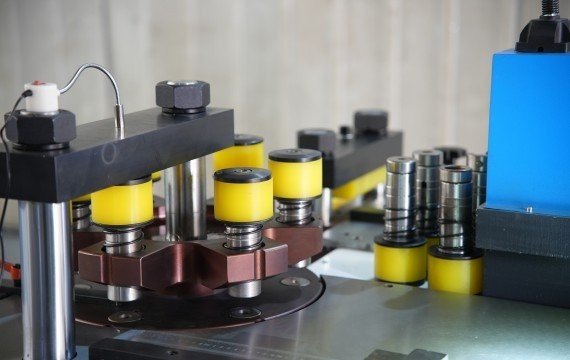
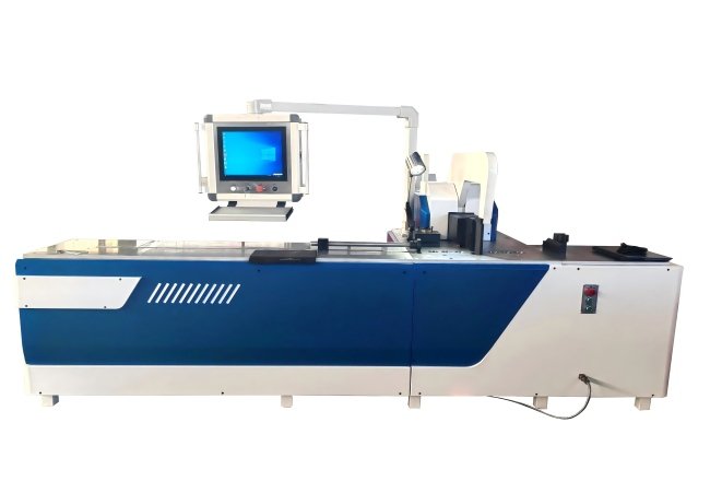
A busbar bending machine forms copper or aluminum busbars into the angles and geometries required for switchgear, transformers, electrical panels, power-distribution equipment and new-energy systems.
The finished bend must match the drawing in angle, bend-line position, inside bend radius, flange dimensions and surface condition. A machine should therefore be evaluated by measured finished parts rather than bending force or controller values alone.
Quick Answer
A busbar bending machine positions a copper or aluminum busbar relative to a bending die and applies controlled force to form the required angle or geometry.
Depending on the configuration, the machine may use hydraulic force, CNC-controlled bending stroke, servo positioning, programmable springback compensation or automatic material handling. The final result should be verified through the released bend angle, bend-line position, inside bend radius, flange dimensions, surface condition and variation across repeated parts.
| Production Requirement | Starting Machine Type | Critical Check |
|---|---|---|
| Mixed custom parts and frequent geometry changes | Dedicated hydraulic busbar bender | Tooling range and setup-to-first-conforming-part time |
| Recurring drawings and repeated bend positions | CNC or servo busbar bending machine | Controlled variables, program recall and finished-part variation |
| Stable, repeated high-volume parts | Automatic busbar bending system | Loading, positioning, unloading and conforming output |
| Punching, shearing and bending in one work area | 3-in-1 busbar processing machine | Bending-unit capacity, station independence and tooling |
What Is a Busbar Bending Machine?
A busbar bending machine is an industrial forming machine designed to bend flat copper or aluminum conductors into drawing-specific shapes.
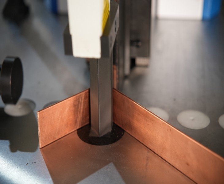
The machine positions the busbar relative to the tooling and applies bending force through a hydraulic, electric or servo-controlled drive system. Depending on the design, it may produce flat bends, edge bends, offsets, U-bends, Z-bends and other customized geometries.
A general press brake may process some busbars when its capacity, tooling and surface protection are suitable. A dedicated busbar bending machine is designed around the dimensions, handling and bending requirements of flat electrical conductors.
How Does a Busbar Bending Machine Work?
| Process Step | What Happens | Buyer Verification |
|---|---|---|
| Material Positioning | The busbar is aligned with the tooling and bend line | Positioning method, backgauge, datum and support |
| Tooling Setup | The required die is installed for the bend geometry | Tool radius, clearance, material and thickness |
| Parameter Setting | Stroke, ram position, backgauge or correction value is set | Which values are controlled and which remain manual |
| Bending | Force forms the busbar around or between the tools | Capacity, alignment and workpiece clearance |
| Force Release | Elastic recovery creates springback | Released finished angle rather than displayed angle |
| Finished-Part Inspection | The completed bend is measured | Angle, bend line, radius, dimensions, twist and surface |
The displayed or programmed value is not automatically the finished bend angle. Material properties, tooling, alignment, clamping and springback all affect the released part.
What Are the Main Types of Busbar Bending Machines?
| Machine Type | What It Describes | Suitable Starting Point | Critical Limitation |
|---|---|---|---|
| Manual or Basic Hydraulic Bender | Manual positioning with mechanically or hydraulically generated force | Mixed low-volume work and simple geometries | Results can depend heavily on setup, tooling and operator positioning |
| CNC Busbar Bending Machine | Programmable control of defined bending variables | Recurring drawings and frequent model changes | CNC does not automatically include feeding, tooling changes or inspection |
| Servo-Positioning Bender | Controlled movement and feedback for a defined axis | Repeated bend positions or backgauge settings | Confirm which axis is servo-controlled |
| Automatic Bending System | Automated loading, positioning, bending or unloading where included | Stable repeated production | The complete automation boundary must be confirmed |
| 3-in-1 Busbar Processing Machine | Punching, shearing and bending integrated into one platform | Mixed operations with limited floor space | Confirm bending-unit capacity separately |
Hydraulic describes how bending force is generated. CNC describes how defined machine variables are programmed and controlled. Servo describes controlled movement and feedback for a specific axis. Automatic describes the extent of material handling and process sequencing.
How Is Busbar Bending Different from General Metal Bending?
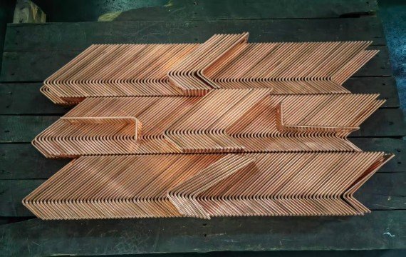
Busbar bending requires attention to material grade and temper, conductor width × thickness, bend direction, inside bend radius, flange dimensions and surface condition.
Compared with general sheet-metal forming, busbar parts may also require:
- Controlled flat and edge bending
- Protection of plated or finished surfaces
- Small bend-to-hole distances
- Accurate electrical-assembly dimensions
- Support for long or heavy conductors
- Clearance for previously formed sections
A general bending machine may be suitable when its tooling, capacity, workpiece support and finished-part results meet the drawing. A dedicated busbar machine may provide a more suitable working layout and tooling system for flat electrical conductors.
Which Finished-Part Results Should Be Verified?
| Inspection Item | What to Measure | Why It Matters |
|---|---|---|
| Released Bend Angle | Angle after the part is removed from the tooling | Includes the effect of springback |
| Bend-Line Position | Actual bend location relative to drawing datums | Affects flange and assembly dimensions |
| Inside Bend Radius | Finished internal radius | Affects geometry and tooling suitability |
| Flange Dimensions | Lengths on both sides of the bend | Determines assembly fit |
| Overall Dimensions | Complete finished-part envelope | Identifies accumulated dimensional error |
| Twist or Deformation | Flatness and torsional distortion | Affects installation and alignment |
| Surface Condition | Scratches, indentations or coating damage | Confirms surface requirements |
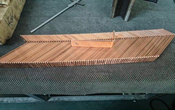
| Repeated-Part Variation | First, middle and final parts | Shows batch consistency |
What Basic Information Should You Confirm?
| Information | Why It Is Needed |
|---|---|
| Material Grade and Temper | Affects force, tooling, springback and surface condition |
| Width × Thickness | Defines operation-specific capacity |
| Bend Direction | Separates flat-bending and edge-bending requirements |
| Bend Geometry | Identifies offsets, U-bends, Z-bends and tooling clearance |
| Inside Bend Radius | Determines tooling and finished geometry |
| Bend-Line Position | Defines positioning and finished flange dimensions |
| Batch Mix | Helps compare manual, CNC and automatic configurations |
| Required Output | Supports complete-cycle and labor evaluation |
| Finished-Part Tolerances | Defines sample-test and FAT criteria |
For detailed machine selection, tooling interference, springback validation and FAT requirements, refer to the Busbar Bending Machine Guide.
Common Problems in Busbar Bending and How You Can Avoid Them
| Problem | Possible Causes | Buyer Verification |
|---|---|---|
| Released angle variation | Springback, material variation, tooling or inconsistent setup | Record material, tooling, correction value and repeated-part results |
| Bend-line deviation | Positioning, datum or alignment error | Measure bend-line position from agreed drawing datums |
| Surface marks | Tooling contact, contamination or excessive localized pressure | Inspect tooling surfaces and approved sample finish |
| Cracking | Material condition, small radius or unsuitable bend direction | Confirm grade, temper, radius and sample results |
| Twist or deformation | Poor support, misalignment or uneven loading | Inspect overall dimensions and flatness |
| Part interference | Incorrect bend sequence or insufficient clearance | Review the complete geometry and tooling sequence |
| Excessive setup time | Frequent tooling or program changes | Measure setup-to-first-conforming-part time |
Dedicated Bender or 3-in-1 Busbar Processing Machine?
| Production Condition | Starting Solution | Critical Check |
|---|---|---|
| Bending is the primary bottleneck | Dedicated busbar bending machine | Tooling range, controlled variables and finished-part results |
| Punching, shearing and bending are all required | 3-in-1 busbar processing machine | Capacity of each station and station independence |
| Several operations must run at the same time | Separate dedicated machines | Staffing, material flow and inspection |
| Stable high-volume punching and cutting with separate bending | Automatic punching and shearing line plus dedicated bender | Complete line balance and material transfer |
An integrated machine may reduce floor space and material transfer, while separate machines may support parallel production. Compare the complete workflow rather than assuming one arrangement is always more efficient.
FAQ
What is the tonnage required for bending copper busbars?
Required bending force depends on material grade and temper, width × thickness, bend direction, inside bend radius, tooling and machine geometry. Rated force alone does not prove that the machine can produce the required finished part.
How do you improve bending accuracy in batch production?
Improve batch consistency by controlling the material specification, tooling, positioning datum, bend program, springback correction and inspection method. CNC can help repeat defined settings, but finished-part results must still be measured.
How much labor can you save with automated bending equipment?
Labor savings depend on which tasks are automated. Record material loading, positioning, tool changes, part rotation, inspection and unloading before comparing operator minutes per conforming part.
What industries use busbar bending machines?
Busbar bending machines are used in switchgear, electrical panels, transformers, power-distribution equipment, busduct systems, energy-storage cabinets and EV charging equipment.
What should you check before choosing a bending machine?
You should evaluate machine capacity, material compatibility, production volume, and whether you need an integrated solution for higher efficiency. If you are working with busbars, choosing the right bending solution is not just about forming metal. It is about labor efficiency and making your production more predictable. The right solution will not only solve bending problems but also improve your entire workflow.