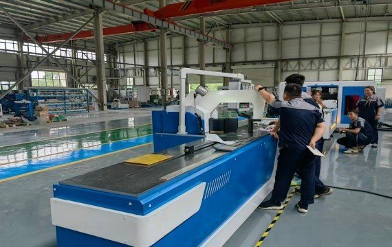
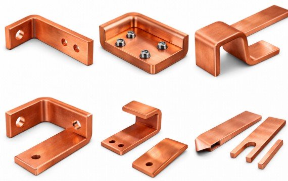
A switchgear busbar manufacturing system integrates engineering data, raw materials, cutting, punching, bending, inspection, part identification, and final cabinet assembly. The system should deliver drawing-conforming copper or aluminum busbars to the correct switchgear project, cabinet, phase and assembly location at the required production rate. Production problems may occur within a single processing station, but they may also occur at the interfaces among drawing release, material preparation, workpiece transfer, tooling, inspection, and assembly feedback.
This guide explains how to design those interfaces and compare different busbar production architectures.
Quick Answer
A switchgear busbar manufacturing system is the complete workflow used to convert approved electrical and mechanical drawings into identified, inspected and assembly-ready busbars.
The system should control five connected flows:
- Engineering and production data
- Raw material and reusable remnants
- Cutting, punching and bending operations
- Inspection and traceability records
- Finished-part delivery and assembly feedback
| System Layer | Required Control | Output |
|---|---|---|
| Engineering Data | Drawing, revision, material, tolerances and part identity | Approved production information |
| Material Flow | Grade, temper, width × thickness, batch and remnant status | Correct material at each operation |
| Processing Flow | Routing, tooling, positioning datum and machine program | Drawing-specific cut, punched and bent parts |
| Quality Flow | First-part, in-process and final inspection | Measured and approved finished parts |
| Traceability | Part ID, drawing, material, tool, program and inspection records | Production history linked to each part or batch |
| Assembly Interface | Cabinet, phase, location, delivery sequence and feedback | Correct parts supplied to switchgear assembly |
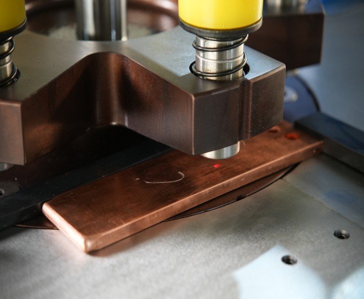
What Is Included in a Switchgear Busbar Manufacturing System?
| System Element | Main Function | Required Record |
|---|---|---|
| Engineering Release | Provides approved drawings and requirements | Drawing number, revision and approval |
| Material Control | Releases the correct conductor material | Grade, temper, dimensions and batch |
| Production Routing | Defines required cutting, punching and bending steps | Routing or process card |
| Equipment | Performs the required operations | Machine model and approved functions |
| Tooling | Produces holes, cuts, radii and formed geometries | Tool code and applicable range |
| Positioning | Locates lengths, holes and bend lines | Datum and positioning method |
| Inspection | Confirms finished-part requirements | Instrument, method and actual results |
| Identification | Links the part to the project and cabinet | Part or batch ID |
| Material Handling | Moves and stores raw, in-process and finished parts | Location and production status |
| Assembly Feedback | Reports fitting, interference or quality issues | Defect type and upstream traceability |
A machine is only one component of the system. Purchasing a more automated machine does not automatically correct missing drawings, unsuitable tooling, unclear routing or inconsistent inspection.
Which Busbar Manufacturing Architecture Fits the Workflow?
| System Architecture | Main Advantage | Main Limitation | Suitable Starting Point |
|---|---|---|---|
| Separate Cutting, Punching and Bending Machines | Operations may run independently or in parallel | More transfers, work-in-process locations and separate positioning datums | Sufficient operators, floor space and parallel demand |
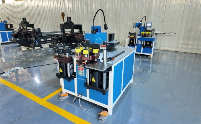
| Hydraulic 3-in-1 Machine | Three operations are available in one work area | Positioning, rotation and inspection may remain manual | Mixed orders and limited floor space |
| CNC or Servo 3-in-1 Machine | Programmed positioning is available on defined axes | Controlled axes, station capacity and manual tasks must be confirmed | Recurring mixed-batch switchgear parts |
| Automatic Punching and Shearing Line with Dedicated Bender | Repeated feeding, punching and cutting can be separated from bending | Material transfer and line balance remain important | Stable punching and cutting patterns with a separate bending process |
| Fully Integrated Automatic System | Agreed handling and processing steps can be sequenced automatically | Greater software, changeover, recovery and integration requirements | Stable product families with sufficient recurring volume |
No architecture is automatically the most stable or efficient. Compare the complete system under the buyer’s actual drawings, material, operators, tooling, inspection and output requirements.
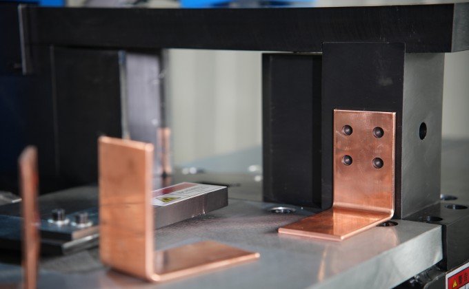
How Should the System Architecture Be Selected?
| Decision Factor | Buyer Question | System Impact |
|---|---|---|
| Drawing Variety | How many unrelated part families are processed? | Affects flexibility and changeover requirements |
| Batch Structure | Are batches short, recurring or continuously repeated? | Affects program, tooling and automation value |
| Required Operations | Are cutting, punching and bending all required? | Determines integrated or dedicated routing |
| Parallel Demand | Must several operations run at the same time? | May support separate dedicated machines |
| Positioning Complexity | How many coordinates and repeated dimensions are used? | Affects CNC or servo value |
| Material Length and Weight | How will long conductors be loaded, rotated and supported? | Affects layout and material handling |
| Tooling Changes | How many dies and forming tools are changed per shift? | Affects changeover design |
| Inspection Load | Which dimensions are inspected and how often? | Affects quality-gate capacity |
| Assembly Sequence | In what order are parts required at the cabinet line? | Affects identification, staging and delivery |
| Floor Space | Is there sufficient infeed, outfeed and WIP space? | Affects equipment arrangement |
| Required Output | What conforming output must reach assembly? | Determines system balance |
| Expansion Plan | Which future materials, dimensions and product families are expected? | Affects capacity reserve |
Final selection should be based on representative drawings and a recorded workflow study—not only on rated force, the word “CNC” or annual production volume.
What Production Information Must Be Released?
| Production Information | Required Content | Risk if Missing |
|---|---|---|
| Drawing Identity | Drawing number, revision and approval | Obsolete or incorrect parts |
| Part Identity | Project, cabinet, phase and part number | Parts delivered to the wrong assembly |
| Material | Grade, temper, width × thickness and surface | Incorrect tooling or process settings |
| Cutting Requirements | Raw length, finished length and tolerance | Assembly fit and material-loss problems |
| Punching Requirements | Hole, slot, pitch and edge distance | Connection and installation problems |
| Bending Requirements | Direction, angle, radius, bend line and sequence | Geometry or tooling interference |
| Surface Requirements | Scratch, indentation, plating or protection limits | Rejected contact or visible surfaces |
| Quantity | Required quantity and permitted setup pieces | Incorrect material and production planning |
| Inspection Plan | Critical characteristics, instruments and sampling | Inconsistent acceptance |
| Delivery Sequence | Required cabinet or assembly order | Excessive sorting and WIP |
The same approved information should be used for programming, tooling preparation, production, inspection and assembly identification.
How Should the Busbar Process Routing Be Defined?
| Routing Step | Required Decision | Output Status |
|---|---|---|
| Material Issue | Release correct grade, section and batch | Material identified |
| Initial Cutting | Cut raw or finished length according to the approved route | Length confirmed |
| Punching or Slotting | Produce holes and slots before or after cutting where approved | Features inspected |
| Bending | Complete flat, edge, offset or complex bends | Geometry confirmed |
| Deburring and Cleaning | Remove unacceptable burrs and contamination | Surface approved |
| Identification | Mark or label the part or batch | Part traceable |
| Final Inspection | Confirm agreed critical requirements | Accepted, reworked or rejected |
| Staging | Store by project, cabinet or assembly sequence | Ready for delivery |
| Assembly Feedback | Report installation or fit-up problems | Upstream corrective action |
The correct order depends on the drawing, machine configuration, tooling and part geometry. Do not assume that cutting, punching and bending must always occur in one fixed sequence.
How Should Material Flow and Workshop Layout Be Planned?
| Layout Item | What to Confirm |
|---|---|
| Raw-Material Storage | Grade, dimensions, batch identity and stock rotation |
| Infeed Space | Longest raw bar, loading method and roller support |
| Machine Access | Operator movement, tooling changes and maintenance |
| Part Rotation | Space required for long or already formed busbars |
| Work-in-Process Area | Status, quantity limit and protection from mixing |
| Inspection Area | Measuring table, instruments and record access |
| Remnant Storage | Identification of reusable material by grade and dimensions |
| Finished-Part Staging | Project, cabinet, phase and assembly sequence |
| Rejected-Part Area | Physical separation and disposition control |
| Material-Handling Safety | Weight, lifting, sharp edges and operator access |
Reducing distance is useful only when the new layout also preserves safe handling, inspection access, material identity and production sequence.
How Should Parts and Production Records Be Traced?
| Traceability Item | Example Record |
|---|---|
| Project and Cabinet | Project number and switchgear panel |
| Part Identity | Part number and phase |
| Drawing | Number and revision |
| Material | Grade, temper, batch and dimensions |
| Machine | Model or station identification |
| Tooling | Tool or die code |
| Program | Name and revision |
| Operator | Operator or shift identification |
| Inspection | Actual measured results and status |
| Rework | Cause, correction and reinspection |
| Final Status | Accepted, rejected or held |
Traceability should allow an assembly problem to be linked back to the drawing, material, machine, tooling, program and inspection result used for the affected part.
Which System-Level Costs Should Be Compared?
| Cost Category | What to Record |
|---|---|
| Direct Labor | Loading, positioning, processing, transfer and inspection |
| Changeover | Program, tooling, material and first-part approval |
| Work in Process | Parts waiting between operations |
| Rework | Cutting, punching, bending and assembly correction |
| Scrap and Remnants | Rejected copper, recoverable scrap and reusable remnants |
| Floor Space | Machines, infeed, outfeed, WIP and inspection |
| Tooling | Included, customized, replacement and regrinding |
| Software | Licenses, backup, updates and access |
| Maintenance | Planned work, spare parts and unplanned downtime |
| Production Delay | Missed assembly sequence or required delivery |
| Documentation | Programming, inspection and traceability records |
Compare the recorded total cost of each architecture. Do not assume that the highest equipment price has the highest lifecycle cost or that the lowest purchase price has the lowest production cost.
How Should You Diagnose the System Before Upgrading?
| Observed Problem | Possible Cause | Verification |
|---|---|---|
| Parts Reach the Wrong Cabinet | Identification or staging control | Traceability and delivery-sequence review |
| Hole Positions Do Not Match Assembly | Drawing, datum, tooling or positioning | Drawing-to-part measurement |
| Bend Geometry Causes Interference | Bend sequence, tooling or drawing | Geometry and tooling-clearance review |
| Excessive WIP Builds Up | Unbalanced station or inspection capacity | Queue and cycle-time record |
| Repeat Orders Differ | Program, drawing, material or tooling revision | Traceability review |
| Assembly Requires Manual Fitting | Combined dimensional or design problem | Link assembly issue to upstream data |
| Changeovers Are Excessive | Tooling, program or batch planning | Complete changeover record |
| Material Is Frequently Mixed | Storage and identification failure | Material-control audit |
| Operators Use Different Methods | Missing standard work or training | Cross-operator process review |
Upgrade the machine only when the verified constraint cannot be corrected through drawings, tooling, routing, layout, measurement, maintenance or work instructions.
Frequently Asked Questions
What Is a Switchgear Busbar Manufacturing System?
It is the complete workflow that converts approved drawings and conductor material into identified, inspected and assembly-ready busbars. It includes data release, material control, cutting, punching, bending, inspection, traceability, staging and assembly feedback.
Can Separate Busbar Machines Form an Effective Production System?
Yes. Separate machines can support an effective system when routing, positioning datums, work-in-process, traceability, inspection and material transfer are controlled.
Is a 3-in-1 Busbar Machine a Complete Manufacturing System?
Not by itself. A 3-in-1 machine integrates processing stations, but the factory must still control drawings, material, tooling, loading, inspection, identification, staging and assembly feedback.
Does CNC Automatically Improve the Complete System?
No. CNC may control defined machine axes or parameters. The benefit depends on the approved program, material, tooling, positioning, remaining manual tasks and finished-part results.
How Can Busbar Parts Be Prevented from Reaching the Wrong Cabinet?
Use controlled part identification and staging linked to the project, cabinet, phase, part number and drawing revision. Verify the identity before production release, final inspection and delivery to assembly.