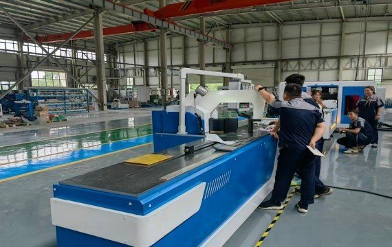
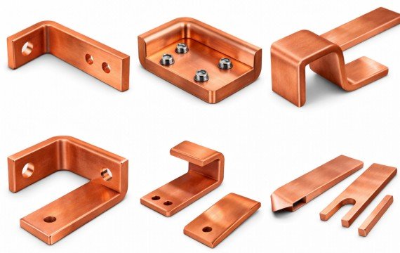
Using a busbar bending machine involves more than entering an angle or activating the hydraulic system. Before bending begins, the operator should confirm the approved drawing, material grade or alloy, temper, busbar width × thickness, bend direction, inside radius, bend-line position, tooling, workpiece support and finished-part acceptance criteria.
The machine should then be controlled through tooling verification, material positioning, a trial bend, first-piece approval, batch monitoring and released-part inspection.
This guide explains how to set up, operate and verify a busbar bending machine for copper and aluminum busbars used in switchgear, electrical panels, transformers and power-distribution equipment.
Quick Answer
Confirm the drawing, material, bend direction, tooling and inspection criteria before starting. Install and align the approved die, support the busbar, establish the drawing datum and enter the required positioning and bending settings. Produce a controlled trial bend, then measure the released angle, bend-line position, inside radius, leg dimensions and surface condition. Begin batch production only after first-piece approval, and revalidate the setup whenever the material, tooling, drawing or machine condition changes.
Stored programs and CNC control can repeat the variables that are actually controlled, but they do not replace material verification, springback confirmation or finished-part inspection.
Should Be Confirmed Before Starting the Machine?
| Pre-Start Item | What the Operator Should Confirm |
|---|---|
| Drawing | Correct drawing number, revision and part identity |
| Material | Copper grade or aluminum alloy and temper |
| Busbar Size | Actual width × thickness |
| Bend Direction | Flat bending, edge bending, offset or another approved form |
| Target Geometry | Released angle, inside radius and bend-line position |
| Short Leg | Minimum finished flange or leg dimension |
| Existing Features | Holes, slots and previous bends near the tooling area |
| Tooling | Correct die code, radius, condition and locking |
| Positioning Datum | Approved edge, end or feature used as the reference |
| Workpiece Support | Roller, worktable, operator support and available clearance |
| Machine Capacity | Confirmed capacity for the required bending direction |
| Program or Setting | Correct job, revision, position and correction value |
| Inspection | Instruments, sampling frequency and acceptance criteria |
| Safety | Guards, emergency stops, work area and approved operating procedure |
Do not begin production when the drawing revision, material, tooling, datum, bend direction, correction method or acceptance criteria remain unclear.
What a Bending Machine Actually Does in Electrical Panel Manufacturing
| Machine Function | What It Controls or Supports | What Must Still Be Verified |
|---|---|---|
| Bending Drive | Generates the movement or force required for bending | Actual material, tooling and supported geometry |
| Tooling Interface | Holds and aligns the bending tools | Tool code, radius, fit, locking and condition |
| Positioning System | Locates the busbar or bend line | Datum, range and measured finished position |
| Bending Axis | Controls stroke, ram position or another supplied variable | Released finished angle |
| Backgauge | Supports repeated material positioning where included | Actual datum and finished leg dimension |
| Program Control | Stores the supplied settings and job data | Correct drawing and program revision |
| Correction Value | Supports material-specific springback adjustment | Result on the released part |
| Worktable and Supports | Support long or heavy conductors | Loading, rotation and formed-part clearance |
| Safety System | Supports operator protection and controlled stopping | Guards, interlocks, emergency stops and restart behavior |
The word “CNC” should not be used as a substitute for a complete machine specification. Confirm which variables are controlled, which movements remain manual and how finished parts are inspected.
How Is a Busbar Bending Machine Used in Production?
| Production Stage | Operator Action | Release Condition |
|---|---|---|
| Drawing Review | Confirm the material, bend geometry, datum, tolerances and inspection method | The approved production reference is clear |
| Machine Inspection | Check the tooling interface, supports, positioning system, guards and machine status | No unresolved machine or safety condition remains |
| Tooling Setup | Install, identify, align and lock the approved tooling | Tooling matches the material and bend geometry |
| Material Positioning | Support the busbar and align the approved datum with the positioning reference | Bend-line and workpiece orientation are confirmed |
| Parameter Setup | Select the approved program or enter the supplied position, stroke or correction values | Settings and revision are recorded |
| Trial Bend | Produce one controlled sample using the approved material and tooling | Machine behavior and initial geometry are acceptable |
| First-Piece Approval | Measure the released finished part | All defined characteristics meet the criteria |
| Batch Production | Monitor the approved process characteristics and record changes | Results remain within the approved limits |
| Stop and Removal | Release pressure, remove and identify the part according to the approved procedure | Finished part is safely transferred for inspection |
What Settings Should Be Recorded?
| Setting | What to Record |
|---|---|
| Drawing and Program | Part number, drawing revision and program revision |
| Material | Grade or alloy, temper and width × thickness |
| Bending Direction | Flat, edge, offset or another approved operation |
| Tooling | Die code, inside radius and tooling revision |
| Positioning Datum | Reference edge, end or feature |
| Target Position | Required bend-line or backgauge position |
| Target Angle | Drawing requirement |
| Correction Value | Approved material- and tooling-specific value |
| Controlled Variable | Stroke, ram position, backgauge or supplied machine variable |
| Operator and Shift | Production traceability |
| First-Piece Result | Actual measured values and approval status |
Do not transfer a stored correction value automatically to a different material grade, temper, thickness, bend direction, tooling radius or material batch without verification.
How Should the First Busbar Be Approved?
| Inspection Item | What to Verify |
|---|---|
| Released Angle | Angle after the part is removed from the tooling |
| Bend-Line Position | Actual position from the approved drawing datum |
| Inside Radius | Finished radius compared with the drawing |
| Short-Leg Length | Required and measured flange dimension |
| Overall Dimensions | Complete finished-part envelope |
| Twist or Deformation | Flatness and torsional distortion |
| Hole and Slot Relationship | Position relative to the bend and finished geometry |
| Surface Condition | Scratches, indentations, cracks or coating damage |
| Assembly Interface | Fit with the breaker, terminal, support or inspection fixture where required |
Batch production should begin only after the approved first-piece characteristics have been measured and recorded.
Common Problems in Busbar Bending Machine Operation
| Observed Problem | Possible Conditions | Immediate Operator Action |
|---|---|---|
| Released Angle Variation | Material condition, springback, tooling, correction value or machine setup | Stop or hold production and compare the actual material, tooling and recorded settings |
| Bend-Line Shift | Incorrect datum, positioning, backgauge or workpiece movement | Recheck the datum and measure the finished bend position |
| Incorrect Short Leg | Positioning error, tooling geometry or drawing setup | Hold the part and measure the finished flange |
| Cracking | Material temper, unsuitable radius, bend direction or surface defect | Stop and review the material and approved tooling |
| Surface Marks | Tool contamination, wear, excessive local contact or poor handling | Inspect and clean the tooling before further production |
| Twist or Deformation | Poor support, misalignment or uneven loading | Check workpiece support and tooling alignment |
| Part Interference | Incorrect bend sequence or insufficient machine clearance | Stop and review the complete drawing and bending sequence |
| Inconsistent Repeated Parts | Material batch, tooling wear, setup, support or machine condition | Compare the first, middle and final parts under recorded conditions |
| Program Mismatch | Wrong part number or outdated revision | Stop, segregate affected parts and restore the approved revision |
Do not automatically attribute every deviation to the bending machine. Review the drawing, material, tooling, datum, support, controlled settings, operator actions and inspection records before confirming the cause.
Manual vs CNC Busbar Bending Machine for Electrical Panel Production
| Control Level | What It May Include | What the Operator Still Verifies |
|---|---|---|
| Basic Hydraulic | Manual positioning and hydraulic bending force | Datum, tooling, position, correction and finished result |
| Digital Assistance | Displayed position, stroke or angle-related value | Actual workpiece position and released part |
| CNC Control | Stored control of defined machine variables | Program revision, material, tooling and inspection |
| Servo Positioning | Feedback control of a specified positioning axis | Finished bend-line and leg dimensions |
| Automatic System | Project-specific feeding, positioning or unloading | Complete material path and finished-part acceptance |
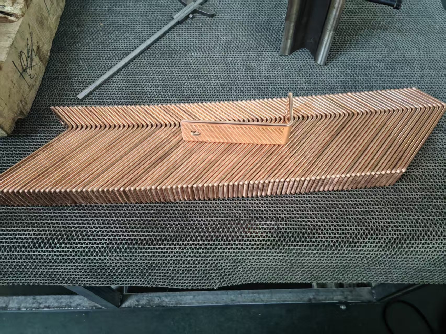
These are control levels rather than fixed quality grades. The correct configuration depends on the drawing, material, bend geometry, batch mix, operator tasks and required conforming output.
When Should the Machine Configuration Be Reviewed?
Review the machine configuration when the required part exceeds the supported flat- or edge-bending capacity, tooling range, positioning range, short-leg limit or workpiece-clearance envelope.
A review is also required when recorded production cannot maintain the released angle, bend-line position, leg dimensions, surface condition or conforming output under the approved setup. Machine replacement should follow verified production evidence rather than a general preference for CNC or automation.
Frequently Asked Questions
What Should Be Checked Before Starting a Busbar Bending Machine?
Confirm the approved drawing, material grade or alloy, temper, busbar width × thickness, bend direction, inside radius, bend-line position, short-leg requirement, tooling, positioning datum, workpiece support and finished-part acceptance criteria. Production should not begin when a critical input or inspection requirement remains unclear.
How Should the Finished Bending Angle Be Verified?
Measure the released finished part after it has been removed from the tooling. The programmed value or controller display is not automatically the finished angle because material condition, tooling, alignment and springback can affect the result.
Can One Busbar Bending Machine Process Different Busbar Sizes?
It may process different sizes when its operation-specific capacity, tooling range and workpiece clearance match the required drawings. Confirm flat bending, edge bending and special geometries separately because a published maximum width × thickness does not automatically apply to every operation.
Does CNC Control Guarantee Consistent Busbar Bends?
No. CNC control can repeat the variables that are actually programmed and controlled. Material batches, tooling condition, springback, workpiece support, setup and inspection can still change the finished result. Verify consistency from measured completed parts.
When Should Bending Tooling Be Replaced?
There is no universal replacement interval. Inspect the tooling according to the machine manual and approved maintenance plan, and review it when surface marks, dimensional changes, visible wear, damage or abnormal contact appear. Confirm the finished result after tooling replacement.
How Should the Setup Be Revalidated After a Material or Tooling Change?
Confirm the new material or tooling identity, restore the approved program or settings and produce a new trial part. Measure the released angle, bend-line position, radius, leg dimensions and surface condition before batch production resumes.
Send Your Busbar Drawings for Machine Setup and FAT Review
Provide one common part drawing, one maximum-size drawing and one complex drawing, together with the material grade or alloy, temper, width × thickness, raw length, bend direction, target angle, inside radius, bend-line position, minimum short-leg length, existing holes, bend sequence, finished tolerances, batch quantity and required output.
Fenghua will review the suitable machine configuration, operation-specific capacity, tooling, positioning method, controlled variables, springback-verification method, workpiece support, remaining manual tasks, representative sample and proposed FAT items. The written review should also identify standard, optional, unsupported or excluded functions before the machine configuration is approved. Send Busbar Drawings for Bending Machine, Tooling and FAT Review