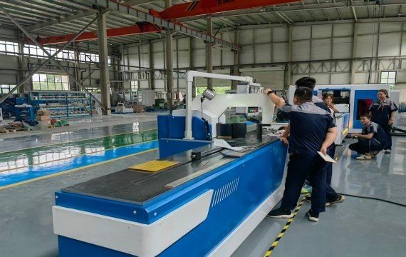
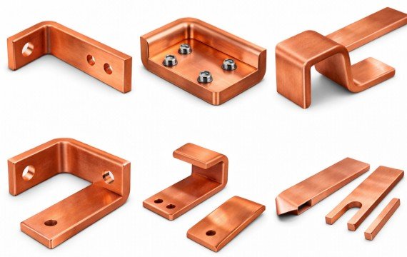
Using a coil winding machine in industrial production involves more than starting the spindle and entering a turn count. Before winding begins, the operator should confirm the approved coil drawing, conductor, insulation, mandrel, winding load, direction, speed, tension method, guiding method, turn counter, safety functions and inspection requirements. During production, the machine should be controlled through trial winding, first-piece approval, defined in-process checks, interruption records and finished-coil inspection.
This guide explains how transformer manufacturers should set up, operate, monitor and verify a coil winding machine during repeated production. For the complete coil-manufacturing process from drawing review to finished-coil inspection, refer to the transformer coil winding process guide.
Quick Answer: How Do You Use a Coil Winding Machine?
Confirm the drawing, conductor, insulation and mandrel before starting. Install the mandrel, load and guide the conductor, then set the winding direction, speed, turn count, tension and traverse where included. Run the machine at low speed to verify feeding, alignment, counting and braking. Approve the first coil before batch production, monitor key process conditions and inspect the finished coil. Stored parameters support repeatability but do not replace operator checks.
What Should Be Confirmed Before Starting the Winding Machine?
| Pre-Start Item | What the Operator Should Confirm |
|---|---|
| Drawing | Correct drawing number, revision and winding identity |
| Conductor | Material, dimensions, insulation, reel and batch |
| Insulation | Correct material, thickness, width and orientation |
| Mandrel | Drawing, connection, locking, alignment and load |
| Tailstock | Position, locking and support condition |
| Payoff | Reel direction, brake, loading and conductor path |
| Guiding | Clean guide surfaces, approved path and initial position |
| Tension | Supplied method, approved setting and operating condition |
| Turn Counter | Starting value, counting direction and memory status |
| Winding Direction | Forward or reverse from the approved reference |
| Speed | Approved initial operating speed |
| Traverse | Travel, pitch and program where included |
| Braking | Controlled stop and spindle-holding condition |
| Safety | Guards, emergency stops, warning devices and work area |
| Inspection | First-piece items, instruments and acceptance criteria |
Do not begin production when the drawing revision, conductor, mandrel, winding direction, turn count, tension method or inspection criteria remain unclear.
Which Machine Functions Should the Operator Understand?
| Machine Function | What It Controls or Supports | What Must Still Be Verified |
|---|---|---|
| Spindle | Rotates the mandrel and coil | Direction, speed, load, vibration and shaft movement |
| Drive System | Provides operating speed and torque | Actual load and approved speed range |
| Brake | Supports controlled stopping | Stopping behavior under the agreed load |
| Turn Counter | Records spindle rotations or turns | Starting value, direction, reverse count and memory |
| Mandrel Interface | Connects and supports the winding tool | Fit, locking, alignment and removal |
| Tailstock | Supports the opposite end of the mandrel | Position, lock and allowable load |
| Payoff | Holds and releases the conductor reel | Reel direction, brake and loading method |
| Tension System | Applies or regulates conductor tension | Actual method, setting and finished-conductor result |
| Guide System | Directs the conductor toward the coil | Contact surfaces, position and conductor path |
| Traverse | Moves the guide across the winding width where included | Controlled axis, travel, pitch and actual arrangement |
| Program Control | Stores or executes included settings | Functions actually controlled and remaining manual work |
| Safety System | Supports emergency stopping and operator protection | Guards, interlocks, warnings and restart behavior |
Do not describe a machine as fully automatic only because it includes a controller, digital counter or variable-frequency drive. The quotation and operating manual should identify every controlled function separately.
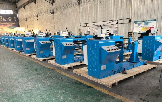
How Coil Winding Machines Are Used in Real Manufacturing Workflow
Coil winding in real production is part of a continuous system process, and each stage influences final stability.
Material preparation is the first factor. Copper wire and aluminum wire mechanical stress, even if their specifications are similar. Differences between material batches’ tension behavior once they pass through the wire guiding system. The condition of the payoff system is stable; the initial winding process begins.
During winding, the tension control system becomes the most sensitive machine. Mechanical brake systems or servo-driven tension systems are commonly used. Stable, the wire may either stretch under excessive force or become loose under insufficient control, leading to structural inconsistency that is not always visible immediately.
Layer formation depends heavily on the mechanical accuracy of the traverse system. Guide rail condition, lead screw precision, and mechanical backlash ensure that the coil layers remain aligned during continuous operation. In long production cycles, even small mechanical wear can gradually accumulate into visible layer deviation.
In CNC coil winding machines, parameters such as turns, speed, and pitch are stored and executed consistently. is not automation itself, but the ability to eliminate variation between operators and production shifts.
Before batch production starts, first piece verification is used to confirm whether the machine is stable enough to release full production. In real factories, this step determines whether the process continues.
During long production runs, stability operating conditions such as material batch variation, temperature changes, guide system wear, and operator shift changes.
Common Problems in Coil Winding Production
| Observed Problem | Possible Causes | Immediate Operator Action | Required Record |
|---|---|---|---|
| Uneven Conductor Arrangement | Guide setup, tension, mandrel alignment, conductor condition or operator correction | Reduce speed or stop at the approved point and inspect the arrangement | Position, time, settings and affected section |
| Loose Winding | Low tension, payoff behavior, mandrel movement or conductor handling | Stop and verify the approved tension and support condition | Tension method, setting and finished result |
| Wire Breakage | Excess tension, damaged conductor, guide surface, small radius, reel blockage or acceleration | Stop safely, secure the coil and identify the break location | Conductor batch, guide path, speed and tension |
| Damaged Insulation | Guide contact, conductor edge, contamination, tension or handling | Stop and evaluate whether repair is permitted | Damage location, cause and disposition |
| Incorrect Turn Count | Counter setup, reverse logic, interruption or manual recording | Hold the part and reconcile the actual turns | Counter value, interruption and correction |
| Incorrect Winding Direction | Setup or drawing-reference error | Stop production and segregate affected parts | Drawing, setup and affected quantity |
| Layer Shift or Telescoping | Mandrel alignment, guide position, tension or speed | Stop and inspect axial movement | Position, settings and observed movement |
| Incorrect Coil Height | Layer spacing, insulation buildup or conductor arrangement | Measure against the defined checkpoint | Actual height and process stage |
| Abnormal Vibration | Mandrel imbalance, support movement, load or spindle condition | Stop the machine and inspect before restart | Speed, load, mandrel and observed condition |
| Coil Cannot Be Removed | Mandrel design, release allowance, deformation or securing method | Do not force removal; review the approved method | Mandrel, dimensions and removal issue |
A defect should not automatically be attributed to the machine. Use the drawing, conductor, insulation, mandrel, guide path, tension, speed, operator action and inspection records to identify the verified cause.
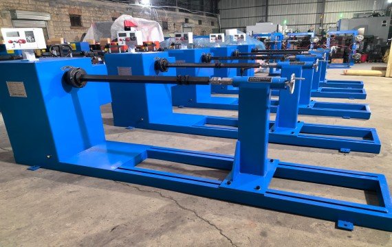
How Do Manual, Motorized and Programmable Controls Differ?
| Control Level | What It May Include | Operator Responsibility | What Must Be Confirmed |
|---|---|---|---|
| Manual Winder | Manual rotation or basic counter | Speed, guiding, tension and stopping | Load, mandrel, operator effort and finished result |
| Motorized Winder | Powered spindle, speed adjustment and counter | Guiding, insulation, leads and inspection | Direction, speed, braking and counter functions |
| Programmable Winder | Stored spindle, traverse or other included settings | Setup verification, material, insulation and inspection | Controlled axes, stored parameters and manual tasks |
| Automatic System | Project-specific automatic functions | Loading, supervision, intervention and acceptance as applicable | Complete cycle boundary and excluded operations |
These are control levels, not fixed quality grades. A simpler machine may be suitable for one approved coil, while a programmable machine may still be unsuitable if its load, mandrel, conductor range, guide travel or process functions do not match the project.
When Does the Existing Winding Machine No Longer Match Production?
Review the machine configuration when the approved coil exceeds the available winding load, spindle torque, mandrel interface, guide travel, conductor range or workshop-handling capacity. A review is also required when repeated production cannot maintain the agreed turn count, dimensions, conductor arrangement, insulation position or lead location under recorded operating conditions.
Machine replacement should follow verified process evidence rather than a general preference for CNC or automation. For model and configuration comparison, refer to the Transformer Winding Machine selection guide.
How Should Shift Changes, Interruptions and Changeovers Be Controlled?
| Production Event | What Must Be Confirmed Before Restart |
|---|---|
| Operator Shift Change | Current drawing, material, turn count, settings, open issues and inspection status |
| Conductor Reel Change | Material, batch, dimensions, insulation, reel direction and tension condition |
| Mandrel Change | Drawing, interface, locking, support, alignment and removal method |
| Product Changeover | Program, direction, turn count, guide position, tension and first-piece criteria |
| Wire Breakage | Break location, affected turns, permitted repair and counter reconciliation |
| Power Interruption | Spindle position, counter memory, conductor condition and approved restart method |
| Parameter Change | Reason, authorization, old value, new value and affected parts |
| Maintenance Work | Reassembled components, guards, calibration and first-piece approval |
Batch production should not resume only because the machine can restart. The operator should confirm the product status, machine status, counter value and affected parts before release.
Frequently Asked Questions
What Should Be Checked Before Starting a Coil Winding Machine?
Confirm the approved drawing, conductor, insulation, mandrel, winding load, payoff, tension method, guiding path, turn counter, winding direction, speed, braking, safety functions and first-piece criteria. Do not start production when a critical input or acceptance requirement remains unclear.
Can a Stored Program Guarantee Identical Coils?
No. A stored program can repeat included settings, but finished results may still be affected by material batches, insulation thickness, mandrel alignment, actual tension, guide condition, operator actions and process interruptions. Compare actual finished-coil measurements.
When Should the Operator Stop the Machine?
Stop according to the approved operating procedure when there is abnormal vibration, unexpected mandrel movement, wire breakage, insulation damage, guide interference, counter error, safety alarm or a measured process deviation. Secure the conductor and identify the affected parts before restart.
How Should Production Restart After a Wire Break or Power Interruption?
Record the interruption point, secure the coil, inspect the conductor and insulation, reconcile the turn count, confirm the machine position and follow the approved repair or restart method. Do not restart only because the controller or counter has recovered.
Does CNC Control Eliminate Operator Inspection?
No. CNC or programmable control may execute defined settings or controlled axes. The operator still needs to verify the drawing, material, mandrel, first piece, insulation, leads, interruptions and finished-coil result.
How Should Coil Winding Repeatability Be Checked?
Produce an agreed sample batch with the same approved conductor, mandrel and settings. Compare the first, middle and final coils for turn count, dimensions, conductor arrangement, insulation position, lead location and surface condition.
Final Note
Coil winding in industrial production is not a simple machine action. It is a controlled manufacturing process; mechanical and control systems must work together continuously. What defines equipment value is not whether it can complete a winding cycle, but operators, materials, and long production periods without introducing cumulative deviation.