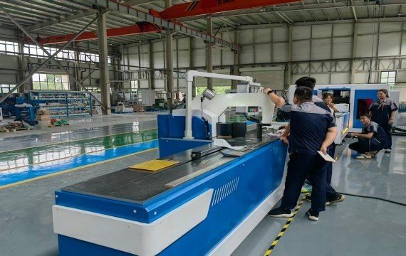
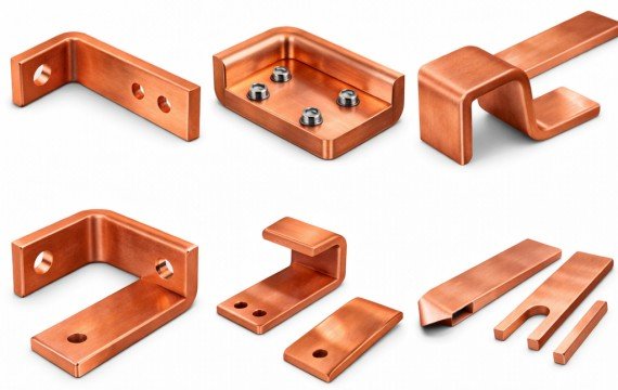
A busbar bending machine is manufactured by integrating the machine frame, bending drive, tooling interface, positioning system, control functions, workpiece support, safety system and electrical components into one approved configuration. Manufacturing quality should not be judged only from machine weight, hydraulic pressure, controller brand or a successful demonstration part. Buyers should verify how the machine was assembled, aligned, tested and documented, and whether it can produce drawing-compliant busbars using the approved material and tooling.
This guide explains which manufacturing and assembly factors may affect finished busbar bends and how buyers should verify the proposed machine through representative samples and factory acceptance testing.
Quick Answer
A busbar bending machine is manufactured through frame fabrication, reference-surface machining, bending-system installation, tooling alignment, positioning and control integration, electrical assembly, safety verification and sample testing.
Buyers should not approve manufacturing quality from appearance or component brands alone. Use representative copper or aluminum busbars to measure the released angle, bend-line position, inside radius, short-leg dimensions, surface condition and variation across several parts. A short FAT confirms immediate capability under recorded conditions. It does not by itself prove long-term machine reliability.
What Should Buyers Verify Beyond the Specification Sheet?
| Published Specification | What It Does Not Prove | Required Evidence |
|---|---|---|
| Nominal Bending Force | Finished-angle accuracy or supported geometry | Drawing-based sample test |
| Maximum Width × Thickness | Capacity for every bend direction and tool | Flat- and edge-bending confirmation |
| Controller Resolution | Released finished-angle tolerance | Measured completed parts |
| CNC Control | Automatic feeding or full-cycle automation | Controlled-axis list |
| Machine Weight | Frame alignment or long-term performance | Manufacturing and inspection records |
| Hydraulic Pressure | Stable finished bends under all materials | Recorded sample results |
| Included Tooling | Suitability for buyer drawings | Itemized tooling list |
| One Successful Sample | Batch repeatability | Agreed short-batch test |
Compare measurable evidence rather than relying only on the words “heavy duty,” “high precision,” “CNC” or “automatic.”
Which Manufacturing Factors Affect a Busbar Bending Machine?
| Manufacturing Area | What Should Be Controlled | Buyer Evidence |
|---|---|---|
| Frame | Geometry, welding sequence and reference locations | Frame drawing and inspection record |
| Machined Surfaces | Tooling, cylinder and positioning references | Dimensional inspection |
| Bending Drive | Cylinder, motor or servo installation | Approved component and assembly list |
| Tooling Interface | Fit, alignment, locking and clearance | Tooling drawing and test |
| Positioning System | Backgauge or material-positioning alignment | Axis and position verification |
| Control System | Actual controlled variables and program functions | Controlled-axis list |
| Workpiece Support | Long-bar support and handling | Layout and maximum-part test |
| Safety | Guards, emergency stops and restart behavior | Safety checklist |
| Electrical System | Voltage, frequency, components and wiring | Electrical drawing and component list |
| Final Assembly | Alignment, fasteners and functional checks | Assembly and test record |
How Should the Frame and Reference Surfaces Be Verified?
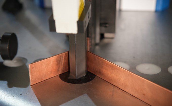
The machine frame supports the bending unit, tooling, worktable and positioning components. Its geometry and assembly condition can influence the alignment of these systems.
Buyers should request confirmation of the reference locations used to install the bending unit, tooling interface and positioning system. Where stress relief, machining or post-weld inspection is claimed, the supplier should identify the actual process and provide available records. Frame weight or steel thickness alone does not prove finished-part accuracy or long-term reliability.
How Should the Bending Drive and Hydraulic System Be Evaluated?
A hydraulic system generates and controls the force or movement required by the bending unit. Its actual role depends on the machine design and the variable being controlled. Finished busbar results may also be affected by material grade and temper, width × thickness, bend direction, tooling, alignment, positioning and springback correction.
During FAT, record the approved material, tooling, program or stroke setting, operating condition and released finished-part measurements. Do not use hydraulic pressure alone as evidence of bending accuracy.
How Does Busbar Tooling Affect the Finished Bend?
| Tooling Item | What to Confirm |
|---|---|
| Bend Type | Flat bending, edge bending, offset or another approved operation |
| Inside Radius | Compatibility with the drawing requirement |
| Material Range | Copper or aluminum grade and temper |
| Busbar Range | Confirmed width × thickness by operation |
| Short Leg | Minimum supported finished flange |
| Hole-to-Bend Distance | Clearance from tooling-contact areas |
| Existing Bends | Interference during later operations |
| Surface Contact | Permitted tool marks and protection method |
| Tool Identification | Code, drawing and approved application |
| Replacement | Lead time, inspection and replacement scope |
Do not accept “standard tooling included” without an itemized list showing the supported operation, material and dimensional range.
Which Conditions Can Change Finished Busbar Results?
| Observed Result | Possible Conditions | Required Verification |
|---|---|---|
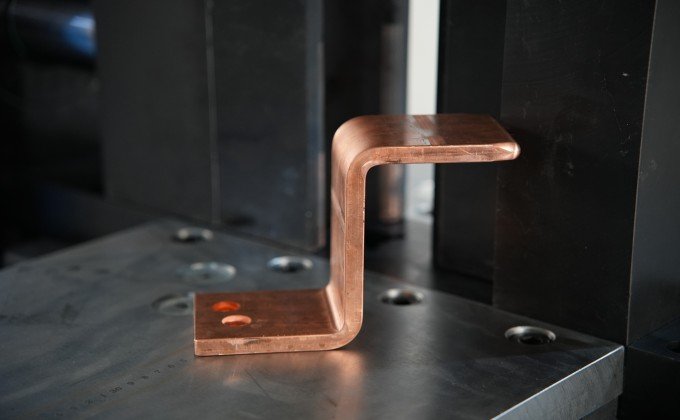
| Released Angle Changes | Material, tooling, correction, positioning or drive condition | Measure several released parts |
| Bend Line Shifts | Datum, backgauge, positioning or operator setup | Measure from approved datum |
| Short Leg Is Incorrect | Positioning, tooling or drawing setup | Measure finished flange |
| Surface Marks Increase | Tool wear, contamination or contact condition | Inspect tooling and finished surface |
| Cracking or Deformation | Material condition, radius or bend direction | Review material and tooling |
| Part Cannot Complete Later Bend | Tooling, frame or worktable interference | Review full drawing and bend sequence |
| Batch Variation Increases | Material batch, tooling wear, setup or machine condition | Compare first, middle and final parts |
How Should a Busbar Bending Machine Be Tested Before Delivery?
| FAT Item | What to Verify | Required Evidence |
|---|---|---|
| Machine Identity | Model, serial number and approved configuration | Nameplate and configuration sheet |
| Drawing | Number, revision and critical characteristics | Approved part drawing |
| Material | Grade or alloy, temper and width × thickness | Material record |
| Tooling | Code, bend type and inside radius | Itemized tooling list |
| Controlled Variables | Stroke, position, backgauge or correction functions | Controlled-axis list |
| Released Angle | Actual angle after removal from tooling | Measured result |
| Bend-Line Position | Actual location from approved datum | Dimensional record |
| Short-Leg Length | Required and measured flange | Inspection report |
| Inside Radius | Finished radius | Inspection result |
| Surface | Marks, indentation, cracks and deformation | Visual record |
| Repeated Parts | First, middle and final results | Comparison sheet |
| Changeover | Last accepted Part A to first accepted Part B | Complete recorded time |
| Operator Tasks | Loading, positioning, rotation and inspection | Manual-work boundary |
| Safety | Guards, emergency stops and restart | Safety checklist |
| Documents | Manual, drawings, settings and backups | Document index |
| Open Issues | Deviations and corrective actions | Signed issue list |
Each item should include the test method, acceptance criterion, actual result, measuring instrument, pass-or-fail decision and buyer-supplier approval.
A short FAT confirms immediate capability under recorded conditions. It does not prove long-term reliability, tooling life or sustained process capability.
How Do Hydraulic, CNC, Servo and Automatic Functions Differ?
| Term | What It Describes | What It Does Not Prove |
|---|---|---|
| Hydraulic | How bending force is generated | Positioning method or finished accuracy |
| CNC | How selected variables are programmed and controlled | Automatic loading or full-cycle automation |
| Servo | Feedback control of a specific axis | Control of every machine function |
| Automatic | Extent of loading, positioning, bending and unloading | Suitability for every drawing or production mix |
Frequently Asked Questions
Does a Heavy Machine Frame Guarantee Better Bending Accuracy?
No. Frame geometry and alignment may support the bending system, but finished-part accuracy also depends on material, tooling, positioning, controlled movement, springback correction and inspection.
Does Higher Hydraulic Pressure Improve Busbar Bending Accuracy?
Not automatically. Hydraulic pressure or nominal force indicates available forming capability. It does not by itself prove the released angle, bend-line position, surface quality or batch repeatability.
Does CNC Control Guarantee Repeatable Finished Angles?
No. CNC can repeat the variables that are actually programmed and controlled. Finished results may still change with material, tooling, alignment, springback and machine condition.
How Should Buyers Compare Two Busbar Bending Machines?
Use the same approved material, drawing, tooling requirement and inspection method. Compare setup time, controlled variables, released angle, bend-line position, short-leg dimensions, surface condition, manual tasks and variation across several parts.
Can One Successful Sample Prove Machine Quality?
No. One sample shows immediate capability under one recorded condition. Use an agreed short batch and compare the first, middle and final parts.
What Documents Should Be Supplied With the Machine?
Confirm the machine configuration, tooling list, component list, electrical drawing, operating manual, maintenance instructions, parameter backup, FAT report and open-issue record.
Final Note
In industrial pipe bending machine manufacturing, you are not evaluating a single bending function. You are evaluating whether the machine can maintain long-term pipe bending accuracy, stable production performance, and repeatability under changing factory conditions. That is what defines whether a machine becomes a reliable industrial pipe bending solution or a source of production variation.