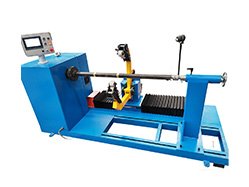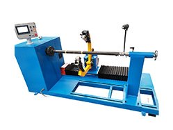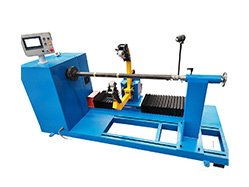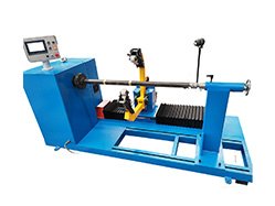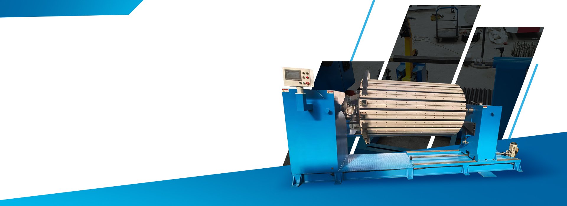
Quick Answer: What Is a Transformer Coil Winding Machine?
A transformer coil winding machine rotates an approved mandrel, former or winding tool while copper or aluminum conductor is guided into the required coil structure.
Depending on the approved configuration, the machine may control spindle speed, winding direction, turn counting, braking, conductor guiding or wire traversing.
It does not independently confirm conductor material, insulation placement, lead positions, finished dimensions or electrical performance. These items must be controlled through the approved drawing, process specification, first-piece inspection and FAT.
Transformer Coil Winding Machine Manufacturer for Drawing-Based Production
FengHua configures transformer coil winding machines according to the approved coil, conductor and mandrel drawings rather than only the transformer power rating.
Before quotation, the engineering review should confirm the transformer application, conductor material, conductor shape and cross-section, coil internal and external dimensions, axial height, winding load, mandrel connection, turn count, winding direction, layer or section structure, insulation process, tension method, guiding method, lead positions and required output.
The technical quotation should identify the exact machine model, operating winding load, spindle speed and torque, shaft and mandrel interface, turn-counting method, braking, tension system, guiding or traverse system, automatic and manual operations, electrical configuration, FAT samples, documentation, warranty and spare-parts scope.
Fenghua Transformer Winding Machine Series
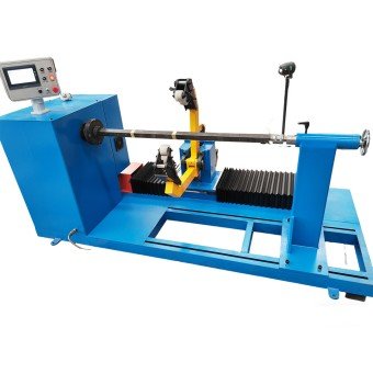
A horizontal winding configuration for large-capacity wire-wound coils. The supplied project reference specifies a winding load of at least 2,000 kg, spindle speed of 0–70 r/min, 5.5 kW motor power and maximum spindle torque of at least 400 N·m.
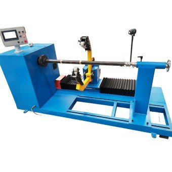
Fenghua’s equipment focuses on coil formation. You have tension control and precise layer-to-layer winding, effectively minimizing winding errors.
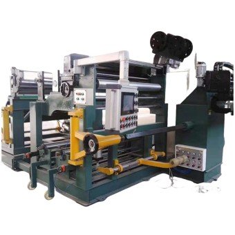
For projects requiring controlled conductor placement across the winding width. Confirm whether the guide is manual, mechanically assisted or servo-controlled, together with its travel, pitch, conductor range and adjustment method.
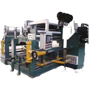
For special coil loads, conductor formats, mandrels, payoff systems, tension devices, guiding systems, operator layouts or workshop integration. Final functions and parameters are defined in the approved technical quotation.
Which Transformer Coil Winding Configuration Should You Choose?
| Production Requirement | Starting Configuration | Main Check |
|---|---|---|
| Heavy horizontal coils | RX-2 horizontal machine | Load, torque, shaft and mandrel |
| Forward and reverse winding | Reversible machine | Counter, braking and memory |
| Controlled conductor placement | Guided winding machine | Guide type, travel and tension |
| Special coils or workflows | Customized system | Function list, layout and FAT |
The machine with the highest spindle speed or most automation is not automatically the correct choice. Match the approved winding load, torque, mandrel, conductor, guiding method and finished-coil criteria.
What Should You Confirm in a Transformer Coil Winding Machine?

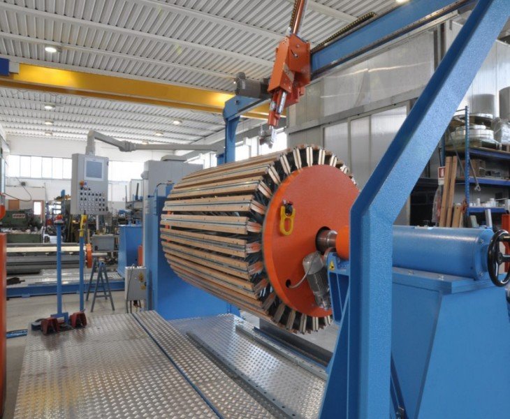
Confirm the maximum operating load, effective spindle length, shaft interface, mandrel connection, tailstock support, locking method and coil-removal procedure.

Confirm the approved speed range under load, maximum spindle torque, acceleration, deceleration, motor braking and spindle-holding condition.

Confirm forward and reverse counting, display range, power-off memory, target-stop method and how the count will be verified during FAT.

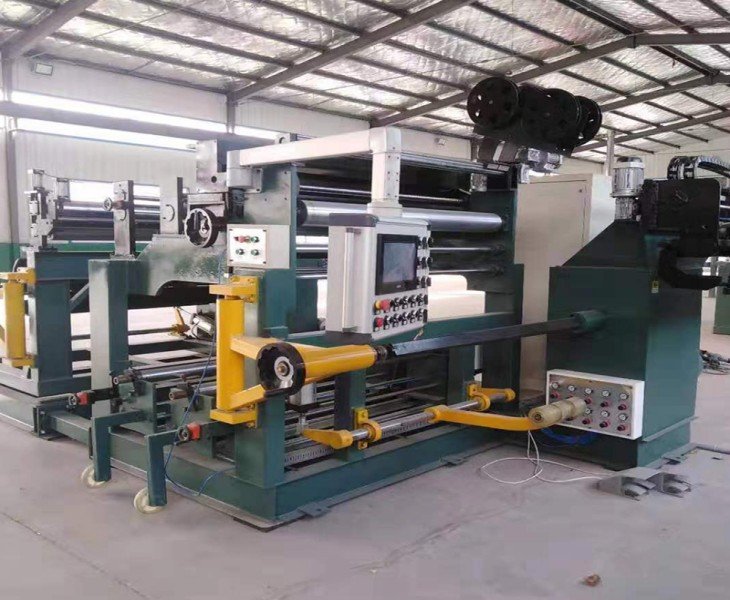
A touchscreen CNC system allows you to configure parameters such as traverse pitch and compensation settings. The equipment supports automatic wire traversing and power-loss memory functions
How Should Winding Control Be Verified?
Do not evaluate winding quality only from the controller display or stored settings.
Confirm the actual supplied functions for spindle speed, winding direction, turn counting, braking, tension and conductor guiding. Where programmable traversing is included, confirm the controlled axis, travel, pitch and synchronization method.
During FAT, use the approved conductor and mandrel to verify turn count, coil dimensions, conductor arrangement, insulation placement, lead positions, surface condition and results from repeated samples.
How Should Different Coil Specifications Be Evaluated?
Changing between transformer coil specifications may require a different mandrel, tailstock position, conductor payoff, tension setting, guiding arrangement, winding direction and process parameters.
The technical quotation should identify the supported conductor and coil ranges, required mandrels, optional guides and first-piece approval method.
For mixed-specification production, include a practical changeover test during FAT and record the adjustment steps, setup time, tools and finished-coil results.
How Should Complete Winding Cycle Time Be Compared?
Do not compare machines using maximum spindle speed alone.
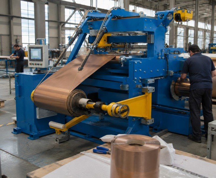
Complete cycle time should include mandrel installation, conductor-reel loading, threading, initial alignment, trial winding, winding, insulation placement, lead handling, controlled stopping, coil removal and finished-coil inspection.
Compare suppliers using the same conductor, mandrel, coil drawing and acceptance criteria. Record the number of operators, setup time, winding time, interruptions, accepted coils and reworked coils.
How Should Changeover and Batch Repeatability Be Verified?
Stored settings can reduce repeated data entry where programmable control is included, but they do not replace verification of the conductor, mandrel, drawing revision, tension, guiding and first finished coil.
For recurring production, use the same approved conductor, mandrel and winding settings to produce an agreed sample batch. Compare the first, middle and final coils for turn count, dimensions, conductor arrangement, lead positions, insulation and surface condition.
For product changeovers, record the mandrel change, payoff adjustment, guide position, tension setting, program or counter setup, first-piece approval and total changeover time.
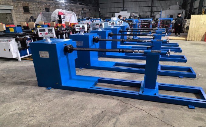
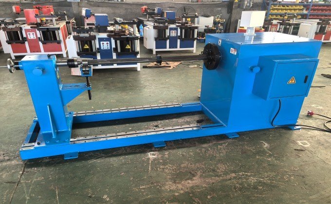
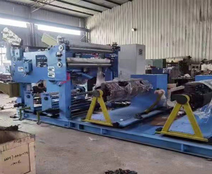
Fenghua CNC’s transformer winding machine features a heavy-duty structural design and a planetary gear transmission system, providing a stable, industrial-grade foundation for winding coils such as those for instrument transformers and reactors.Fenghua’s integrated system helps enhance coil forming stability, meeting the demands of your long-term, continuous industrial production environment.
How Should Machine Structure and Conductor Guiding Be Evaluated?
Machine structure should be evaluated under the agreed winding load, speed and mandrel configuration.
During FAT, inspect spindle and tailstock alignment, mandrel support, abnormal vibration, braking, spindle locking and conductor path.
Where a guide or traverse system is included, inspect conductor spacing, crossed turns, layer transitions, axial position, lead position and any conductor or insulation damage on the finished sample coil.
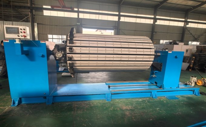
FengHua’s automatic transformer winding machine’s control system employs a progressive acceleration/deceleration curve, eliminating the risk of sudden starts or stops, thus improving the overall capacity and accuracy of your production workshop.
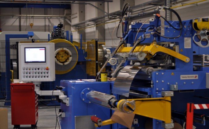
FengHua’s automatic transformer winding machine, through an independent wire laying mechanism and synchronous control of the main shaft, achieves precise setting of the corresponding wire laying step distance for different wire diameters, reducing the risk of rework on your production line.
It winds approved copper or aluminum conductors onto a mandrel, former or winding tool to produce transformer coils according to the released drawing and process specification.
The supplied RX-2 requirement specifies forward and reverse spindle rotation, reversible turn counting and power-off memory. The approved FAT should verify direction, counter behavior and braking under the agreed load.
No. The complete result also depends on starting value, reverse counting, interruptions, stopping and operator actions. Verify the displayed count against a known-turn test during FAT.
Compatibility depends on the conductor shape, cross-section, insulation, payoff, tension, torque, guiding system and coil drawing. Both materials should be reviewed separately.
No. Finished conductor arrangement also depends on tension, guide setup, mandrel alignment, winding speed, conductor condition, insulation and first-layer positioning.
Provide the transformer application, conductor material and dimensions, coil internal and external dimensions, axial height, winding load, mandrel drawing, number of turns, winding direction, insulation structure, guiding requirement, output target and local power supply.