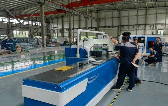
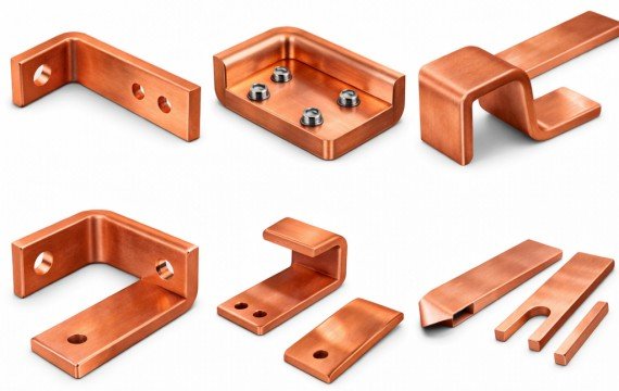
The manufacture of your switchgear copper busbars should begin according to approved drawings and material specifications. Typical manufacturing processes include cutting, punching, bending, deburring, and inspection. This guide explains each stage and the production inspection items you should verify.
Quick Answer: How Is a Copper Busbar Made?
A copper busbar is manufactured through drawing review, material verification, process routing, cutting or shearing, punching or slotting, bending, deburring, cleaning, inspection and part identification.
The exact order is not fixed for every part. It depends on the drawing, selected datum, machine configuration, tooling access, bend geometry and surface requirements.
Typical Copper Busbar Manufacturing Process
| Process Stage | Required Input | Main Output | Inspection Focus |
|---|---|---|---|
| Drawing Review | Approved drawing and revision | Defined production requirements | Dimensions, datums, tolerances and sequence |
| Material Verification | Grade, temper, width × thickness and batch | Released raw material | Identity, dimensions and surface |
| Process Routing | Machine, tooling and geometry | Approved operation sequence | Datum and tooling access |
| Cutting or Shearing | Required raw or finished length | Cut workpiece | Length, squareness, burr and deformation |
| Punching or Slotting | Hole and slot drawing | Punched holes and slots ready for inspection | Position, size, pitch, edge distance and burr |
| Bending | Bend direction, angle, radius and sequence | Finished geometry | Released angle, bend line, dimensions and surface |
| Deburring and Cleaning | Processed part | Safe, clean edges and surfaces | Burrs, contamination and damage |
| Final Inspection | Drawing and inspection plan | Accepted or rejected part | All critical characteristics |
| Identification and Staging | Project, cabinet, phase, part and inspection status | Assembly-ready part | Part ID, quantity and production status |
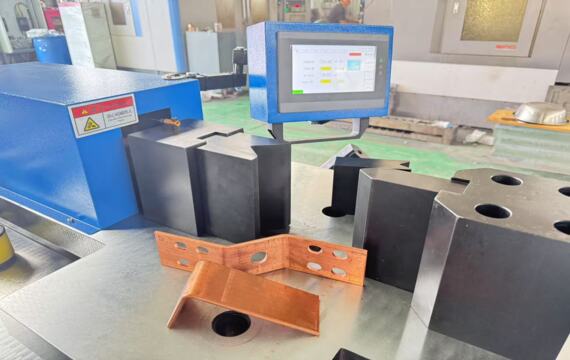
What Should Be Confirmed Before Processing?
| Production Input | What to Confirm |
|---|---|
| Drawing | Number, revision, approval and part identity |
| Material | Copper grade, temper and batch |
| Section | Actual width × thickness |
| Raw Material | Raw-bar length and surface condition |
| Finished Length | Target, tolerance and datum |
| Holes and Slots | Size, position, pitch, edge distance and quantity |
| Bending | Direction, angle, inside radius, bend line and sequence |
| Surface | Scratch, indentation, coating or plating requirements |
| Quantity | Required parts and permitted setup pieces |
| Inspection | Critical features, instruments and sampling |
| Identification | Project, cabinet, phase and part number |
The approved electrical drawing or material specification should define the copper grade and section. The fabrication team should verify the released material rather than independently selecting conductor size from the machine’s maximum capacity.
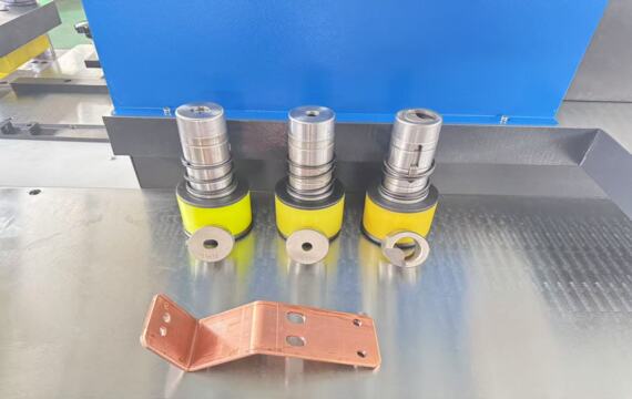
Material And Busbar Dimensions
The width, thickness, grade, and temper of the busbar will affect cutting forces, punching capacity, bending dies, workpiece support, and handling. You should confirm the specific requirements for each process based on the drawings.
Copper Busbar Manufacturing Process
Cut or Shear the Copper Busbar
| Cutting Check | What to Record |
|---|---|
| Finished Length | Target and measured value |
| Squareness | Agreed measurement across the cut end |
| Burr | Location and maximum permitted condition |
| End Deformation | Visible or measured deformation |
| Surface Condition | Scratches or indentation |
| Remnant | Material identity and reusable length |
Cutting or shearing determines the length of the busbar blank or finished product required by your drawings. You need to determine the target length using the approved drawing references and confirm the material support and positioning methods.
Punch Holes and Slots
You should punch and slot according to the approved drawing references. You need to confirm the hole diameter, slot size, pitch, edge distance, and orientation.
| Punching Check | What to Record |
|---|---|
| Hole Position | Position from approved drawing datums |
| Finished Diameter | Actual hole size after punching |
| Center-to-Center Pitch | Distance between required features |
| Edge Distance | Finished hole edge or center to material edge |
| Slot Size | Length, width and orientation |
| Burr and Deformation | Condition around the punched feature |
| Surface Condition | Tool marks, indentation or coating damage |
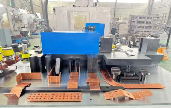
Bend the Copper Busbar
Bending should follow the approved bending direction, bend line, inner radius, finished angle, and operating sequence shown on the drawing. You need to check that the selected die can machine the required geometry, ensuring that there is no interference at short legs, U-bends, Z-bends, or nearby holes.
The angle set in the program or the angle displayed should not be considered the result. After bending, you should measure the released generatrix.
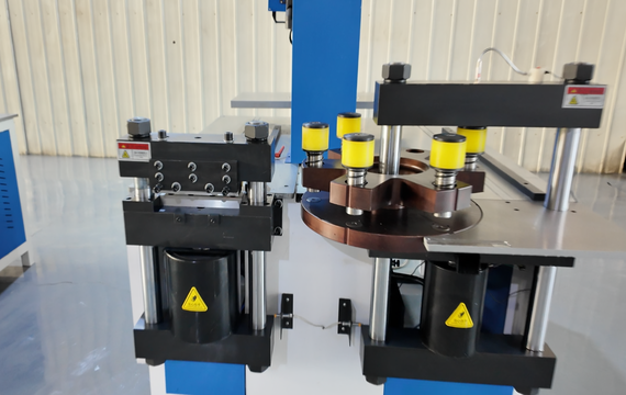
Deburr, Clean And Inspect The Finished Busbar
After cutting, punching, and bending, you should deburr and clean the finished busbars, and inspect and assemble them according to the approved drawings. Deburring should cover cut ends, punched holes, slots, and other machined edges that may produce sharp burrs or material protrusions. Burrs or edge deformation can affect part fit, contact surfaces, insulation clearances, and subsequent assembly.
You should clean the busbar surface and inspect it for scratches, dents, excessive deformation, or other visible damage incurred during machining and handling. You should verify critical dimensions and part markings according to the drawing requirements.
| Inspection Item | What You Should Check |
|---|---|
| Cut Edge | Burrs, deformation and end condition |
| Punched Holes And Slots | Burrs, finished size and orientation |
| Surface Condition | Scratches, dents and visible processing damage |
| Finished Length | Dimension from the specified drawing datum |
| Hole Position | X/Y coordinates, pitch and edge distance |
| Bend Angle | Released finished angle after bending |
| Bend Position | Bend line and finished dimensions against the drawing |
| Part Identification | Part number, drawing number, revision or project identification |
The first piece and subsequent spot checks of your mass production should use the same measurement methods and drawing references to ensure that cutting, punching, and bending results are judged according to uniform standards. If your busbars require subsequent electroplating, insulating coating, or other surface treatments, you may need to confirm the required surface finish and the areas to be shielded.
3-In-1 Busbar Machine Vs Separate Machines
Your manufacturing route also affects whether cutting, punching and bending should be completed in one integrated machine or on separate equipment. Compare workflow, station independence and required parallel production before selecting the layout.
| Workflow Requirement | 3-In-1 Machine | Separate Machines |
|---|---|---|
| Mixed cutting, punching and bending | Reduces transfers between separate machines | Requires workpiece transfer between operations |
| Limited workshop space | Combines several operations in one footprint | Requires more floor space and material movement |
| Parallel cutting, punching and bending | Confirm whether stations can operate independently | Separate machines can support simultaneous operations |
| Repeated CNC punching and shearing | Confirm positioning and cycle limitations | Dedicated CNC punching/shearing may better support repeated production |
For a full machine-selection comparison, see our 3-in-1 busbar processing machine configurations rather than using this workflow table alone.
Frequently Asked Questions
Can A Supplier Process Your Copper Busbar Drawing Before You Buy The Machine?
Yes. You can send representative copper or aluminum busbar drawings to the supplier before ordering the machine. Ask the supplier to process samples using material and dimensions close to your actual production. Check finished length, hole position, bend angle and visible burrs against the agreed drawing requirements. For higher-value equipment, include these representative parts in the FAT plan.
What Should Be Included In A Busbar Processing Machine FAT?
A FAT should use representative busbar drawings and agreed materials. Confirm cutting, punching and bending results separately where those operations are included. Record finished dimensions, hole positions, bend angles, tooling used and any remaining manual steps. The FAT plan should define the sample quantity, measuring method and acceptance criteria before the machine is completed.
How Should Drawing Revisions Be Controlled For Repeat Busbar Orders?
Use a clear drawing number and revision for every released busbar part. When the drawing changes, check whether the CNC program, hole coordinates, cutting length, bend position or tooling also needs to change.
What Documents Should Be Delivered With A Busbar Processing Machine?
Your overseas procurement should include confirmation of the technical documentation scope before shipment. You may need to confirm the operation manual, electrical drawings, hydraulic schematics, parameter backups, mold lists, spare parts lists, and maintenance documentation.
Final Thoughts
Fenghua’s machine configuration reduces manual operations, minimizes rework, and supports stable production for electrical cabinets, switchgear, and power distribution equipment.
Please send us your busbar drawings, thickness, width, hole layout, bending angles, and daily production volume. Fenghua will recommend the most suitable busbar processing machine solution based on your actual manufacturing requirements.