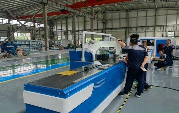
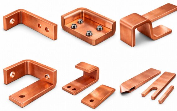
Choose a copper busbar machine from your actual drawings, material specifications, and required output—not from price, rated force, or the word “CNC” alone. This guide explains how to compare hydraulic 3-in-1 machines, servo-positioning systems, automatic CNC punching and shearing lines, and dedicated bending machines. It also covers operation-specific capacity, tooling, workshop layout and factory acceptance testing.
Quick Answer
Choose a copper busbar machine from your actual drawings, material grade and temper, width × thickness range, required operations, finished-part tolerances, production mix and conforming output. Verify punching, shearing, flat-bending and edge-bending capacity separately.
| Production Requirement | Recommended Configuration | Key Check |
|---|---|---|
| Mixed orders and low-volume production | Hydraulic 3-in-1 machine | Station capacity, tooling and positioning time |
| Repeated models and frequent changeovers | Servo-positioning 3-in-1 machine | Controlled axes, program recall and changeover time |
| Repeated punching and fixed-length cutting | Automatic CNC punching and shearing line | Feeding range, gripper dead zone and conforming output |
| Complex or repeated bending | Programmable busbar bending machine | Tooling clearance, springback compensation and variation across repeated finished parts |
| Wide, thick or long busbars | Heavy-duty busbar machine | Operation-specific capacity, material support and maximum-size sample test |
Final machine selection should be confirmed through representative drawings, material information, sample processing and an agreed factory acceptance test.
Which Copper Busbar Machine Configuration Do You Need?
Different factories have different busbar-processing requirements. Start by defining the required operations, drive system, positioning method, and material-handling automation. Selecting the right configuration helps avoid unnecessary capital expenditure on functions that do not improve your production workflow.
Hydraulic, CNC, servo positioning, automatic and 3-in-1 do not describe mutually exclusive machine types. One machine may use hydraulic force, CNC control, servo positioning and manual material loading at the same time.
How Should Operation-Specific Capacity Be Verified?
A published maximum width × thickness does not prove that every station can process that maximum material size. Punching, shearing, flat bending and edge bending must be confirmed separately according to material grade, temper, tooling and drawing geometry.
| Operation | Specifications to Confirm | Buyer Risk |
|---|---|---|
| Punching | Material, width × thickness, hole and slot sizes, edge distance and tooling reach | Hole positions may be inaccessible |
| Shearing | Material, width × thickness, finished length, tolerance, burr and deformation | Rated capacity may not ensure acceptable cut quality |
| Flat Bending | Width × thickness, angle, radius, flange length and tooling | Angle deviation or tooling interference |
| Edge Bending | Width × thickness, bend direction, radius and machine clearance | Insufficient force or clearance |
| Complex Bending | Bend sequence, spacing, finished shape and frame clearance | Formed sections may collide with the tooling or machine |
| Material Handling | Raw bar length, finished-part size, weight and roller support | The part may be difficult to load, position or unload |
| Finished-Part Quality | Dimensional tolerance, angle tolerance, burr, surface and repeatability | Catalog capacity may not produce conforming parts |
The supplier should record the confirmed limits of each operation in the quotation, technical agreement, tooling list and FAT plan.
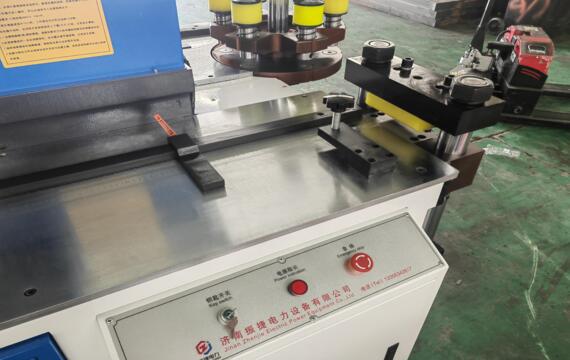
You should verify whether the equipment shares a single hydraulic power system or if each station is equipped with an independent power unit. Understanding how simultaneous operation of multiple stations affects processing pressure, production speed, and hydraulic oil temperature is crucial. Separate punching, shearing, and bending machines may be better suited for high-volume production. Processing on individual machines can reduce idle time and boost the workshop’s overall capacity.
Hydraulic busbar processing machines are often well suited to smaller batches, flexible orders and frequently changing dimensions. They can accommodate changing specifications without the investment required for a more complex automated line. For wide, thick or hard-temper copper, consider a heavy-duty configuration with sufficient processing force and application-specific tooling.
How Should You Select Control and Positioning?
You need to verify the specific CNC capabilities. While a machine might support the storage of bending parameters, you need to clearly understand which processing axes are automatically controlled and which dimensions are merely displayed on the digital panel for operator reference.
Digital measurement systems help operators read dimensions more accurately and reduce errors associated with manual visual checks, though they do not necessarily automate the movement of the copper busbar itself. CNC copper busbar processing machines equipped with servo positioning systems offer distinct advantages; the program storage function allows for the saving of frequently used processing parameters, thereby reducing the time spent repeatedly entering dimensions.
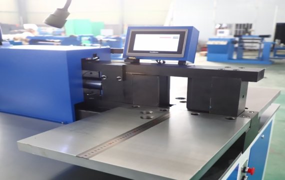
It is recommended that you ask the supplier to demonstrate the machine using your own processing drawings; this provides a clearer understanding of how well the equipment fits your production workflow. Positioning accuracy is the difference between the commanded and measured position. Repeatability is the variation when the same movement is performed repeatedly. Controller resolution is only the smallest displayed or commanded increment and should not be presented as machine accuracy.
How Much Material-Handling Automation Do You Need?
Automation features for copper busbar processing equipment can include servo positioning, automatic feeding, automatic punching, automatic shearing, barcode recognition, and automatic unloading. Each function requires individual assessment; different automation configurations address different needs, and an incorrect choice could inflate equipment costs.
Automated copper busbar punching and shearing lines can reduce manual labor and increase production throughput. Automatic feeding provides the greatest value when material sizes, hole patterns and batch quantities are repeatable. Its benefit may be lower when unrelated short batches require frequent die changes, special handling or manual correction. When selecting automatic feeding equipment, you must consider factors such as the gripper dead zone, minimum raw material length, minimum finished product length, and scrap handling methods. These details impact material utilization rates and actual production costs. The choice of automation configuration should be based on your order types, staffing arrangements, and daily production volume.
Review the detailed specifications of the 500 kN hydraulic 3-in-1 busbar processing machine when this capacity range matches your drawings. Published capacities are initial selection references. Published accuracy values should be confirmed against the controlled axis, test method, material dimensions, tooling and first-part correction procedure. Final selection requires review of the buyer’s drawings, material grade and output.
How Do Material Grade, Width and Thickness Affect Capacity?
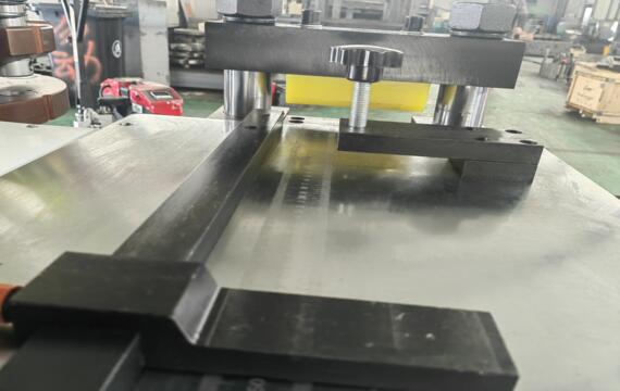
Provide the actual copper grade, temper, hardness and surface condition. Bare copper, tinned copper, plated copper and aluminum may require different die clearances, surface-protection methods and bending compensation settings.
Material condition affects punching force, burr formation, cutting quality, tool wear and bending springback. Ignoring these differences can lead to rework, surface damage and assembly interference.
| Item | Specification |
| Product Type | 500 kN Hydraulic 3-in-1 Busbar Processing Machine |
| Processing Functions | Punching / Hydraulic Shearing / Bending |
| Processing Material | Copper Busbar / Aluminum Busbar |
| Busbar Capacity | 15–200 mm Width / 3–15 mm Thickness |
| Punching Capacity | Ø4.3–Ø35 mm |
| Bending Range | 0–90° |
| Rated Force / Hydraulic Pressure | 500 kN / 31.5 MPa |
| Feeding And Measurement | Manual Feeding / PLC-Assisted Digital Measurement |
| Recommended Workpiece Length | Up to 4,000 mm With Suitable External Roller Support |
| Power Supply / Installed Power | 380 V / 50 Hz / 3 Phase / 10–12 kW |
| Machine Size / Net Weight | Approx. 1,700 × 1,700 × 1,600 mm / Approx. 2,100 kg |
Published width and thickness values are model-level references. Operation-specific limits for punching, shearing, flat bending and edge bending should be confirmed according to material grade, tooling and workpiece drawings.
How Do Hole Layout and Tooling Affect Punching?
Do not evaluate punching capability only by maximum hole diameter. Confirm hole-to-edge distance, minimum hole-center pitch, slot dimensions, throat depth, punch reach, clamp clearance and gripper dead zones. Check whether the published hole-position range is measured from the busbar edge, end, or machine datum.
For slotted holes, confirm the slot length, width, orientation and die clearance. Review the tooling list to identify which holes use included standard dies, which require optional standard tools and which need custom dies. During sample testing, measure hole position, diameter, burr height, edge deformation and surface scratches.
How Do Bend Geometry and Springback Affect Selection?
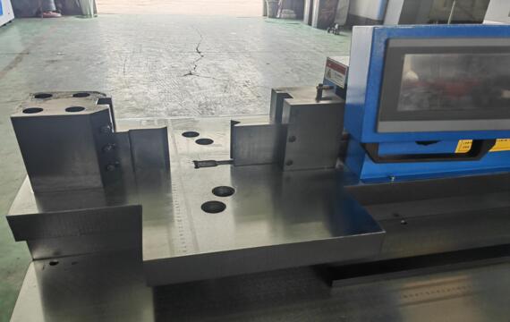
A stated 0–90° bending range does not prove that every busbar geometry can be produced. Flat bends, edge bends, offsets, U-bends and Z-bends require different tooling and machine clearance.
Springback depends on material grade, temper, thickness, bend direction and inside bend radius. The displayed or programmed angle may therefore differ from the released finished angle.
Confirm how the machine controls and corrects the bending angle. A published angle value should state whether it represents the commanded angle, finished-angle accuracy or repeatability after first-part correction. For U-bends, Z-bends and closely spaced bends, review tooling and frame clearance from the actual drawing and process a sample before final acceptance.
Which Copper Busbar Machine?
The right machine depends on the finished electrical product, typical busbar dimensions, hole patterns, and bend volume. Use the following recommendations as starting points only. Final selection should be confirmed using your actual material and representative drawings.
Which Configuration Fits Switchgear and Control Panel Production?
Switchgear and control panel production commonly involves repeated cutting lengths, circuit-breaker mounting holes and defined bend positions. A 3-in-1 machine can reduce workpiece movement by completing shearing, punching and bending in one working area.
For recurring cabinet models, servo positioning and stored programs can reduce repeated marking, data entry and setup. Submit drawings from several cabinet models so the supplier can verify hole positions, required tooling and station capacity.
Which Configuration Fits Transformer and Power Distribution Production?
Transformer and industrial power-distribution manufacturers often process wider, thicker and longer busbars. These parts place greater demands on operation-specific machine capacity, tooling strength, and material support.
A heavy-duty machine should be evaluated separately for shearing, punching, flat bending and edge bending. Long busbars may also require external roller supports to reduce sagging and feeding misalignment. Test the maximum-size material with the proposed tooling before confirming the machine configuration.
Which Configuration Fits Energy Storage and EV Charging Equipment?
Energy storage and EV charging equipment often uses compact busbar parts with small edge distances, dense hole patterns and multiple bends. For recurring product models, CNC or servo positioning can improve changeover efficiency and reduce repeated setup.
Machine selection should also consider gripper reach, clamping clearance, near-edge deformation, and bending interference. Review the complete drawing group to identify shared tooling, custom dies and which parts are better suited to a servo bending machine or an automatic punching and shearing line.
| Application | Typical challenge | Starting configuration | Critical check |
| Switchgear and control panels | Repeated holes and cabinet variants | 3-in-1 machine with optional servo positioning | Hole-position repeatability, program recall and station independence |
| Transformers and power distribution | Wide, thick and long busbars | Heavy-duty machine with external roller support | Operation-specific capacity and maximum-size sample test |
| Energy storage systems | Dense holes and compact bends | CNC or servo positioning with flexible tooling | Edge distance, clamping clearance and bending interference |
| EV charging equipment | Similar parts with frequent changeovers | Program management and quick-change tooling | Shared tooling, custom dies and changeover time |
Record every operation required for a representative workpiece, including the number of cuts, holes, slots and bends. Measure the complete cycle from material loading to final inspection of the finished part.
How Should You Match The Machine to Your Production Plan?
Review both your current product range and the maximum dimensions expected within the next two to three years. This reduces the risk of purchasing a machine that becomes undersized after your order specifications expand.
How Should You Estimate Conforming Parts per Shift?
To evaluate equipment capacity, you must focus on the quantity of conforming parts. Record the complete processing steps for a representative workpiece, including the number of shearing, punching, and bending actual test duration should be measured from the moment material loading begins until the final inspection of the finished product is completed.
The testing includes real-world production, die changes, first-article adjustments, and product model changeover times. Ignoring these elements can easily lead to an overestimation of production capacity.
| Output Evaluation Item | Recommended Method | Buyer Check |
| Shift Output Formula | Available production minutes × planned utilization ÷ average minutes per conforming part | Use conforming parts, not theoretical machine cycles |
| Processing Time | Measure from material loading to completed inspection | Include positioning, cutting, punching, bending, tool changes and unloading |
| Planned Utilization | Apply only to production losses not already included in the measured cycle | Avoid deducting inspection or changeover losses twice |
| Test Batch | A 10–20-part batch can be used as a short-run screening test, but it does not prove long-term reliability, tooling life or sustained process capability. | Record conforming parts, rejected parts and total elapsed time |
| Test Conditions | Use the actual material grade, tooling and representative drawing | Record operator count, hole quantity, bend quantity and tool changes |
How Much Workshop Space and Utility Capacity Do You Need?
The equipment’s external dimensions do not represent the actual installation space required. You must reserve sufficient area for accommodating the longest copper busbars, unloading finished parts, operator movement, and equipment maintenance. Insufficient infeed or outfeed space can cause difficult handling, positioning errors and safety risks.
The equipment installation plan should account for roller support positions, tooling storage areas, clearance for opening electrical cabinets, and access space for hydraulic system maintenance. A well-planned layout reduces unnecessary material movement and provides access for tooling changes, electrical work and hydraulic maintenance.
How Should You Evaluate Tooling and Technical Support?
Tooling configuration determines the equipment’s ability to process your actual products. You need to confirm a comprehensive tooling list with the supplier, covering shearing blades, round-hole punches, slotting punches, and bending dies. This list should include quantities, tool-changing methods, and future replacement costs for each set of tools. Confirming the tooling scope before purchase helps prevent missing dies, unsuitable clearances and unexpected tooling costs after delivery.
| Technical delivery item | Required content | Buyer value |
| Operation and maintenance manuals | English operating instructions, safety procedures, lubrication points, preventive-maintenance tasks and model-specific service intervals | Supports operator training, routine machine operation |
| Electrical and hydraulic drawings | Electrical circuit diagrams, terminal layouts, hydraulic schematics and component references | Replace components accurately |
| Spare parts buyer value | Component names, brands, model numbers, installed quantities, recommended stock quantities and long-lead critical parts | Reduces ordering errors and shortens downtime. |
| CNC program and parameter backup | Program files, machine parameters, backup procedures, recovery instructions and required storage media | Prevents loss of production settings after controller failure, replacement or software corruption |
| Tooling documentation | Standard tooling list, die sizes, tool drawings, installation instructions, clearance requirements and replacement information | Supports safe tool changes, repeat orders and future tooling procurement |
| Software access and licenses | Software versions, license status, passwords, user access levels, supported file formats | Prevents software-access problems and unexpected license restrictions after delivery |
| FAT and inspection records | Test material, drawings, test conditions, measurement methods, results, deviations, corrective actions and approval status | Creates a verifiable acceptance baseline and records whether agreed requirements |
| Remote technical support | Support channels, service language, response process, remote-diagnostic method, access authorization and fault-reporting requirements | Reduces troubleshooting time while keeping remote access controlled by the buyer |
| Training and commissioning records | Installation checks, operator training content, maintenance training, attendee names and unresolved action items | Confirms knowledge transfer for future operator training |
| Warranty and service terms | Warranty period, covered components, exclusions, labor responsibilities, travel costs and claim procedure | Clarifies lifecycle responsibilities and prevents disputes after delivery |
| Packing and delivery documentation | Packing list, machine weight, lifting points, center-of-gravity information, shipping-condition inspection | Supports safe unloading, installation and verification of all supplied items |
For a CNC copper busbar processing machine, buyers should confirm that program backups, parameter files and recovery instructions are included before delivery.
Frequently Asked Questions
How Long Does It Take to Change Busbar Punching or Bending Tools?
Tool-change time depends on the machine structure, tooling type, and operator experience. Standard round-hole punches may be changed relatively quickly. Slotting, edge-bending and custom-forming tools may require additional alignment, testing and first-part inspection. Record the time from the last conforming part before the tool change to the first conforming part after the change.
Can One Machine Process Both Copper and Aluminum Busbars?
Many busbar machines can process both copper and aluminum, but the same capacity limits, tooling clearances and process settings should not be assumed for both materials. Material grade and hardness affect die clearance, cutting quality, springback and surface marking. Confirm the supported aluminum grade, test both materials, and retain separate approved samples and processing settings.
What Safety Features Should a Copper Busbar Machine Include?
Safety requirements depend on the machine configuration and destination market. Typical features may include emergency stops, guards, foot-pedal protection, safety interlocks, overload protection and operating warnings. Verify every supplied safety function during FAT and confirm the applicable certifications and technical documents.
How Often Does a Hydraulic Busbar Machine Need Maintenance?
Maintenance frequency depends on operating hours, workload, workshop conditions, and hydraulic-system design. Routine maintenance may include checking hydraulic oil, inspecting hoses and seals, cleaning the machine, lubricating specified points, and monitoring tooling wear. Follow the model-specific maintenance schedule and operating-hour intervals supplied with the machine.
What Information Should Be Included in a Copper Busbar Machine Quotation?
A complete quotation should identify the exact model, standard and optional functions, operation-specific capacities, control system, included tooling, electrical configuration and reviewed drawings. It should also state the Incoterm, lead time, packing method, FAT scope, installation responsibilities, training, warranty exclusions and recommended spare parts.
Final Thoughts
The right copper busbar processing machine depends on copper busbar drawings.Send FengHua three representative drawings: one common part, one maximum-size part and one complex part. Include the material grade, width, thickness, hole layout, bend geometry and required output. Our engineering team will review operation-specific capacity, standard and custom tooling, possible interference and the most suitable machine configuration