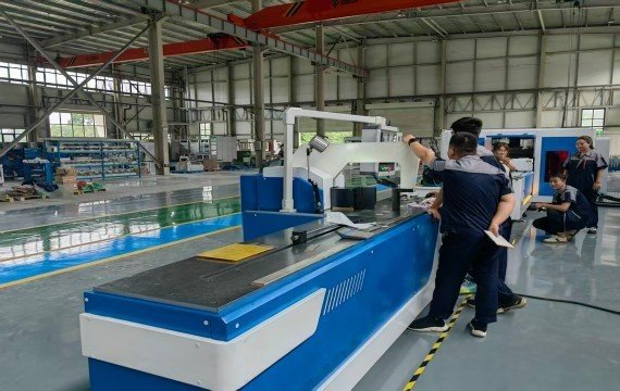
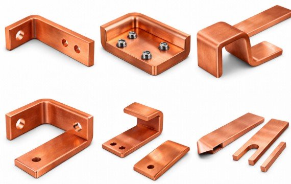
A copper busbar machine for switchgear must produce approved electrical and mechanical drawings. Machine selection should begin with the approved busbar drawing, material grade or temper, and the required punching, shearing, and bending operations. This guide explains how switchgear manufacturers and machine importers can compare machine architecture, tooling, representative drawings, and defined production requirements.
Quick Answer
Choose a copper busbar machine for switchgear by matching drawings, production mix and required output.
An integrated 3-in-1 machine performs punching, shearing, and bending on a single platform. Separate machines allow individual operations to run independently when the workflow, staffing and workpiece handling change. CNC or servo functions may be used where programmed positions or controlled movement are required, while an automated line may combine controlled feeding with selected processing operations.
Verify operation-specific capacity, controlled axes, tooling access, material handling, and finished-part results using your actual switchgear busbar drawings.
| Production Architecture | How Processing Is Arranged | What The Buyer Should Verify |
| Separate Or Dedicated Machines | Punching, shearing and bending are completed on separate equipment | Capacity by operation, workpiece transfer, support and operator workflow |
| Integrated 3-In-1 Machine | Punching, shearing and bending stations share one machine platform | Capacity, tooling, positioning and permitted station operation |
| Automated Busbar Processing Line | Controlled feeding is combined with selected processing operations | Loading, clamp dead zones, feeding, controlled processes, unloading and remaining manual tasks |
CNC describes programmed control, servo describes controlled motion or positioning, and hydraulic describes force generation. These functions may machine architectures.
What Is A Copper Busbar Machine For Switchgear?
A copper busbar machine is equipment used to punch connection holes and slots, shear busbars to length and form drawing-specific bends for switchgear, control panels and distribution equipment.
These operations may be performed on separate machines or on an integrated 3-in-1 platform. An integrated platform keeps several operations within one working area, although material measurement, rotation, repositioning and inspection may still remain manual depending on the configuration.
Buyers should therefore compare the actual processing sequence, positioning method, tooling, operator requirements and finished-part results—not the number of functions listed on the machine name alone.
What Processing Requirements Do Switchgear Copper Busbars Create?
Different cabinet types and electrical components have different requirements for hole positions, lengths, and bending structures. What you really need to confirm is: your copper busbars are being machined according to the drawings.
Punching Connection Holes
Switchgear busbars may require round holes, slots or application-specific features for circuit breakers, terminals, supports and bolted connections.
For every representative part, record the finished hole diameter, slot dimensions, center-to-center pitch, hole-to-edge distance, material width and thickness, surface requirements and drawing tolerance.
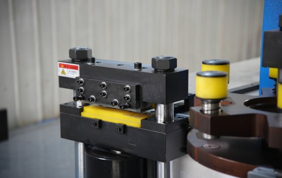
Rated punching force and maximum hole diameter do not prove that every required coordinate is reachable. Verify throat depth, tooling clearance, stripper access, clamp or gripper dead zones and the available positioning range. The sample test should inspect finished hole position, diameter, ovality, edge deformation and maximum burr height.
Shearing Switchgear Busbars to Length
The shearing operation must produce the finished length shown on the drawing while maintaining acceptable squareness, cut-face quality and deformation.
Verify the positioning method, usable measuring range, minimum finished length, blade condition, raw bars and finished parts. If positioning remains manual, include measuring, alignment, and first-part correction in the complete cycle time.
Sample inspection should cover finished length, cut squareness, burrs, cut-face condition, and visible recording only the machine stroke time.
Bending Switchgear Busbars
Switchgear busbars may require flatwise bends, edgewise bends, offsets, U-bends, Z-bends or several bends within a compact assembly space.
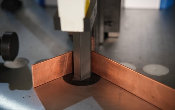
Confirm the material grade and temper, width and thickness, bend direction, inner radius, minimum leg length, bend-to-hole distance, spacing between adjacent bends and the geometry of previously formed sections.
A machine may have sufficient bending force but still be unable to complete the operation because the workpiece collides with the tooling, frame, or worktable. Complex parts should therefore be reviewed through a tooling and interference drawing.
Because material condition and tooling affect springback, measure the finished angle after the part has been released from the tooling. Finished-bend acceptance should use the released part and the agreed drawing-based measurement method rather than controller resolution or nominal hydraulic force alone.
What Copper Busbar Machine Configurations Are Used For Switchgear Production?
Different switchgear factory structures. There’s no fixed configuration for copper busbar processing machines. You need to consider the copper busbar drawings, order volume, and operator availability. Switchgear production may use separate machines, an integrated 3-in-1 platform, or an automated processing line depending on the required processing route, production mix, and material-handling structure.
Dedicated Punching, Shearing and Bending Machines
Separate machines may be appropriate when punching, shearing, and bending each have enough workload to support a parallel process without waiting for another station.
The buyer should compare additional floor space, workpiece transfer, operator requirements, infeed and outfeed support and process coordination. Separate equipment provides limited production value when operators or inspection capacity are insufficient to keep the machines working in parallel.
Integrated 3-in-1 Copper Busbar Machine
An integrated 3-in-1 machine places punching, shearing, and bending stations on one machine platform. It may allow operators to move busbars between separate work areas and production.
Integration does not provide automatic positioning or continuous processing. The workpiece measuring, feeding, rotation, and transfer between stations.
Confirm the capacity and tooling of each station separately. Stations share one hydraulic power unit, whether concurrent operation is permitted and whether simultaneous use affects pressure, cycle stability, or hydraulic-oil temperature.
CNC Or Servo-Controlled Busbar Equipment
CNC or servo-controlled equipment becomes more valuable when approved dimensions, positions, or processing sequences recur.
Depending on the machine, the controlled variable may be punching position, cutting length, feeding position, backgauge position, bending stroke or angle correction. CNC control should not be assumed to include automatic material positioning.
Ask the supplier to list every controlled axis, controlled variable, usable travel, feedback method, program-storage function and operation that remains manual. Demonstrate program creation, drawing-revision identification, recall, backup, restoration and changeover between two actual switchgear parts.
Automated Busbar Processing Line
An automated punching and shearing line may be suitable when hole patterns, cutting lengths and raw-material formats remain stable and repeated production volume justifies controlled feeding.
Automatic feeding does not mean that loading, tooling changes, inspection, sorting, bending and unloading are all automatic. The quotation should identify every automatic, assisted and manual step.
Verify maximum feeding travel, clamp dead zones, minimum raw-bar and finished-part lengths, remnant handling, long-bar support, unloading method, and complete cycle time. Compare conforming parts rather than theoretical strokes per minute.
What Should Be Defined From A Switchgear Busbar Drawing?
The most useful machine representative switchgear busbar drawings. Different drawing features affect punching, shearing, bending, tooling, and positioning in different ways.
| Drawing input | Supplier must review | Why it matters |
| Material grade and temper | Supported material condition and test basis | Affects force, cutting behavior and springback |
| Surface condition | Tool-contact and protection method | Tinned or coated busbars may be marked |
| Regular and maximum width × thickness | Punching, shearing, flatwise- and edgewise-bending capacity | Maximum values may not apply together |
| Holes and slots | Tooling, reach and positioning method | Maximum punching force does not prove feature access |
| Hole-to-edge and hole-to-hole positions | Tooling clearance and finished tolerance | Affects reach, deformation and assembly fit |
| Finished cutting length | Positioning and material support | Affects measurement and workshop layout |
| Bend geometry and direction | Tooling and bend sequence | Flatwise, edgewise, U- and Z-bends require different access |
| Inner radius and minimum leg | Tooling feasibility and interference | Short legs may require special tooling |
| Bend-to-hole distance | Deformation and tooling clearance | Closely spaced features may be unsupported |
| Finished-part tolerances | Measurement and acceptance method | Separates machine positioning from finished results |
| Batch size and drawings per shift | Recommended control and automation | Determines whether setup or cycle time is more important |
| Required conforming output | Complete-cycle testing method | Prevents comparison by nominal speed alone |
Submit one common part, one maximum-demand part and one complex part. If the maximum punching, shearing, flatwise-bending and edgewise-bending conditions occur on different drawings, include one representative drawing for each condition.
How Should a Switchgear Busbar Machine Be Tested Before Purchase?
Use the buyer’s actual copper grade and representative drawings whenever possible. The test should begin with material loading after the finished part has been inspected. A single selected sample does not prove repeatability or production output. Run an agreed short batch and measure final parts.
| FAT item | What to record | Acceptance basis |
| Test conditions | Machine model, serial number, drawing revision, material, tooling, operators and batch size | Approved FAT plan |
| Punching | Hole position, diameter, pitch, edge distance, ovality and burr height | Drawing tolerance |
| Shearing | Finished length, squareness, cut quality and deformation | Drawing or approved sample |
| Bending | Released angle, bend-line position, inner radius, leg dimensions and twist | Drawing tolerance |
| Complex-part clearance | Complete bending sequence | No interference or unsupported step |
| Program functions | Save, recall, edit, revision identification, backup and restore | Approved machine scope |
| Changeover | Last conforming part of conforming part of Model B | Agreed complete changeover time |
| Batch output | Total time, conforming, corrected and rejected parts | Agreed output and quality result |
| Safety | Guards, emergency stops, foot-switch protection, interlocks and restart behavior | Approved safety checklist |
The buyer should receive the drawing-review conclusion, tooling list, measurement records,measuring-instrument information, and test conditions video.
Frequently Asked Questions
What Electrical Configuration Should an Importer Confirm Before Ordering?
Provide the actual factory voltage, frequency, phase, allowable voltage variation and grounding system—not only the destination country. Confirm installed power, motor and hydraulic-pump compatibility, control voltage, and compressed-air demand where applicable. The quotation, machine nameplate, manuals and electrical drawings should show the same approved configuration.
What Spare Tooling Should a Distributor Stock for Demonstrations?
Spare tooling should match the demonstration-machine model and common local busbar requirements. Initial stock may include frequently used round punches and dies, slot tooling, cutting blades and application-specific bending tools.
Record the tooling size, compatible material and thickness range, installed quantity, replacement price and replenishment lead time. Custom tooling should be managed separately from routine spare parts.
When Does a Demonstration Busbar Machine Make Sense for a Distributor?
A demonstration machine is useful when the distributor has enough local demand, trained operators, workshop space and technical capacity to conduct repeatable sample tests.
Select a configuration for local busbar dimensions and representative bend geometries. Prepare one common part, one maximum-demand part, and one complex part, together with approved tooling and measurement records. Do not choose the highest automation level unless local customers can use and verify the additional functions.
Submit Your Switchgear Busbar Drawings for Review
Choose a copper busbar machine by matching material, connection holes, cutting lengths, bend geometries, finished-part tolerances, batch structure, and required conforming output. FengHua will prepare a written review covering the recommended machine configuration, operation-specific capacity, controlled axes, standard and custom tooling, positioning method, material-handling limitations, interference risks, unsupported features, and proposed FAT items.