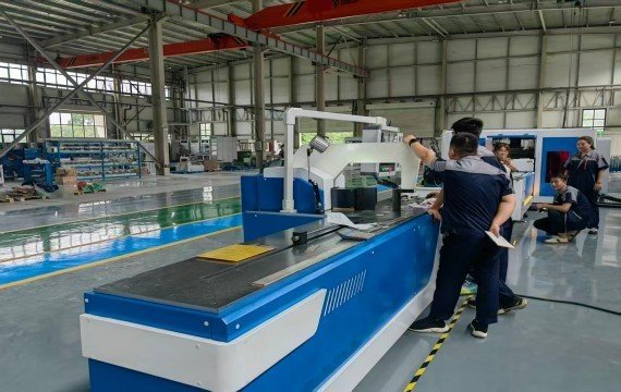
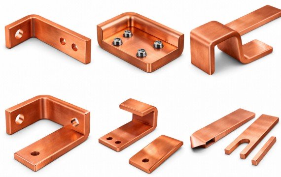
A busbar bending machine forms copper or aluminum busbars into flat bends, edge bends, offsets, U-bends, Z-bends, and other drawing-specific geometries. The correct machine must match the material grade and temper, width and thickness, bend direction, inner radius, angle tolerance, bend-line position, batch size, and required output.
Quick Answer
Choose a busbar bending machine by comparing five areas: operation-specific capacity, supported bend geometries, tooling and machine clearance, controlled axes and springback-compensation method, and finished-part results under your actual material conditions.
Do not select a machine from bending force or a published angle-accuracy value alone. Verify the released finished angle, bend-line position, leg dimensions, inner radius, surface marks and batch variation using your drawings, material and agreed inspection method.
Quick Busbar Bending Machine Selection
| Production requirement | Recommended starting solution | Key buyer check |
| High-mix custom parts with frequent geometry changes | Dedicated hydraulic or programmable bender with flexible quick-change tooling | Setup-to-first-conforming-part time, tooling range and manual positioning |
| Recurring medium batches and frequent model changeovers | CNC or servo-controlled busbar bending machine | Controlled variables, program revision, positioning method and first-part correction |
| Stable repeated parts and high production volume | Automatic busbar bending system | Loading, positioning, unloading, tooling-change time and conforming output |
| Punching, shearing and bending in one compact work area | 3-in-1 busbar processing machine | Bending-unit capacity, station independence, tooling and material |
How Does a Busbar Bending Machine Work?
A busbar bending machine positions the workpiece relative to the tooling and applies bending force through a hydraulic, electric or servo-controlled drive system.
The controlled variable may be bending stroke, ram position, backgauge position, material position, angle correction, or a combination of these variables. The machine and tooling force the busbar load.
After the bending force is released, part of the elastic deformation is recovered as springback. The finished result therefore depends on the controlled movement, tooling geometry, material condition, clamping, alignment and springback-correction method.
What Are The Main Types Of Busbar Bending Machines?
Hydraulic, CNC, servo, and automatic busbar bending system.
Hydraulic describes how bending force is generated. CNC describes how one or more machine variables are programmed and controlled. Servo describes the controlled actuation and feedback of a specific axis, which may be the bending axis, backgauge or material-feeding axis. Automatic describes the extent of loading, positioning, bending, unloading and production sequencing.
A CNC busbar bending machine may use hydraulic bending force, servo-controlled positioning and manual material loading at the same time.
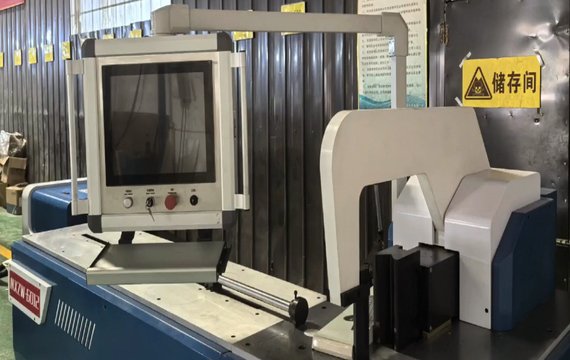
Hydraulic Busbar Bending Machine
A hydraulic busbar bending machine uses a hydraulic cylinder to generate bending force. The machine may use manual positioning, digital assistance, CNC control or servo-controlled positioning.
Operation-specific capacity, tooling flexibility, positioning method, setup time, and required output—not on the hydraulic drive label alone.
Before purchasing, confirm flat- and edge-bending capacity separately, the supported tooling range, positioning method, and the finished-part results under the buyer’s actual material conditions.
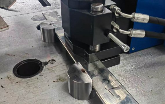
CNC Busbar Bending Machine
A CNC busbar bending machine may control bending stroke, finished-angle correction, backgauge position, material position or a combination of these variables. CNC control should not be assumed to include automatic feeding or material positioning.
Ask the supplier to list every controlled axis, the controlled variable, travel range, feedback method, program-storage capacity, and operations that position.
Automatic Busbar Bending Machine
An automatic busbar bending system is most valuable when drawings repeat, material formats remain stable and the required production volume justifies automatic loading, positioning or unloading.
For high-mix production, verify program-change time, tooling-change time and setup-to-first-conforming-part time before assuming that higher automation will improve output.
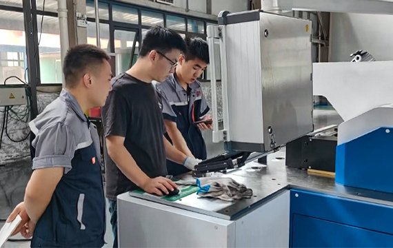
3-in-1 Busbar Processing Machine
A 3-in-1 busbar processing machine is an integrated fabrication platform rather than a separate bending-control category. Its bending unit may be manually positioned, digitally assisted, CNC-controlled or servo-controlled.
Confirm the bending-unit capacity and tooling separately from the punching and shearing stations. Stations share one hydraulic power unit, and whether concurrent operation is permitted.
How To Choose The Right Busbar Bending Machine
Which Drawings and Material Information Should You Provide?
Provide one common part, one maximum-size part and one complex part. If flat bending, edge bending, offset bending and compact U- or Z-bending occur on different parts, include a representative drawing for each condition.
Each drawing should identify the drawing number and revision, material grade and temper, surface condition, width, thickness, bend direction, inner radius, bend-line position, angle tolerance, linear tolerance, holes and finished-part geometry.
Do not assume that the machine’s maximum published width and thickness can be processed together in both flat and edge bending.
How Should Production Mix and Output Affect Automation?
For high-mix custom work, tooling flexibility and setup-to-first-conforming-part time may be more important than automatic feeding.
Recurring medium batches can benefit from program storage, controlled positioning and approved material-specific correction values.
Stable repeated production may justify automatic loading, positioning or unloading. Compare complete cycle time and conforming parts rather than relying only on theoretical bending speed.
How Do Bend Geometry and Tooling Clearance Affect Selection?
Flat bends, edge bends, offsets, U-bends, Z-bends and torsion bends require different tooling and machine clearance.
Provide the minimum leg length, bend-to-hole distance, spacing between adjacent bends and the geometry of previously formed sections.
A machine may have sufficient bending force but still be unable to complete the part because the workpiece collides with the frame, tooling or worktable during a later bend. Complex parts should be reviewed through a tooling and interference drawing before the machine is ordered.
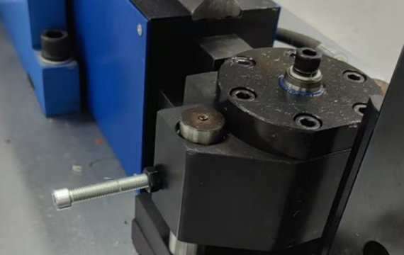
How Should Tooling and Sample Testing Be Verified?
Use the buyer’s actual material or an agreed equivalent to verify the finished angle, bend-line position, inner radius, leg dimensions, surface condition and springback correction.
The test should record the material grade and temper, busbar dimensions, bend direction, tooling, program revision, correction value, operator count, setup time and complete cycle time.
One finished sample does not prove repeatability. Run an agreed-upon short batch and measure the final parts.
Which Busbar Bending Accuracy Values Should Be Separated?
Bending-axis positioning accuracy is the difference between the commanded axis position and the measured machine position under a defined test method.
Machine repeatability is the variation when the same controlled movement returns to the same target repeatedly under equivalent conditions.
Controller resolution is the smallest increment commanded. It should not be presented as finished-angle accuracy.
Finished-angle accuracy is the difference between the drawing target and the released angle measured on the completed busbar.
Batch angle variation is the range produced across several parts under the same recorded production conditions.
How should finished busbar bends be inspected?
Measure the busbar after it has been released from the tooling. Record the finished angle, bend-line position, leg dimensions, inner radius, parallelism, or twist where surface marks are.
The report should identify the drawing number and revision, material grade and temper, busbar width and thickness, bend direction, tooling, machine program, measuring instrument, instrument resolution and calibration status.
What is busbar bending springback?
Busbar bending springback is the change between the angle produced under load and the finished angle measured after the bending force is released. The programmed angle or ram position is therefore not automatically the finished-part angle.
The amount of springback may change when the material grade, temper, hardness, thickness, bend direction, inner radius, tooling geometry or material batch changes.
Which factors change busbar springback?
| Factor | Why it matters | Buyer or operator check |
| Material grade and temper | Different material conditions produce different elastic recovery | Record grade, temper, supplier and material batch |
| Width and thickness | Changes the required force and deformation | The actual dimensional range |
| Flat or edge bending | The bending direction changes section | Confirm capacity separately |
| Inner bend radius | Tool geometry influences deformation and finished shape | The tool radius to drawing requirements |
| Tooling condition | Wear, clearance can change the result | Inspect tools and record tool identification |
| Material surface | Tinned, coated or soft aluminum surfaces may mark or deform | Use an approved surface sample |
| Process settings | Stroke, overbend and correction affect the released angle | Record the approved program and correction value |
| Material batch | Nominally identical material may produce different springback | Repeat first-part approval after a batch change |
How can springback be compensated?
Springback can be compensated for by overbending, correcting the bending stroke, using approved material-specific programs, or measuring the angle during the bending process.
Manual correction relies on the programmed setting and the released finished angle. Stored material programs can reduce repeated setup, but they remain valid only for the material, tooling and process conditions under which they were approved.
A system with angle measurement or closed-loop correction may reduce first-part adjustment, but the supplier should demonstrate when correction is applied and whether the system measures the loaded angle or predicts the released finished angle.
When Should Apringback Settings Be Revalidated?
Repeat first-part approval whenever the material grade, temper, thickness, supplier batch, surface coating, bending direction, inner radius, tooling or clamping condition changes.
For a long production run, measure selected parts at agreed intervals. A stable machine position does not prove that the finished angle remains stable when tooling wear or material conditions change.
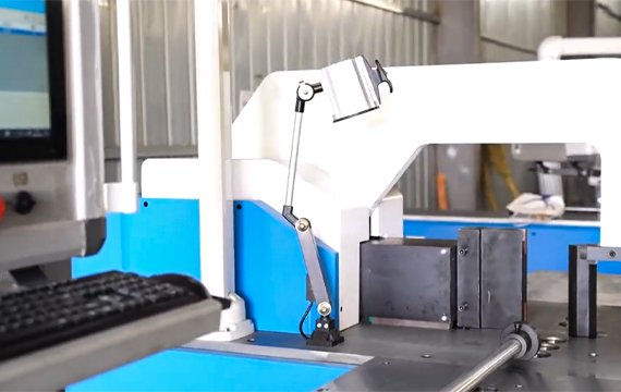
Which Applications Use Busbar Bending Machines?
Requirements regarding copper busbar dimensions, bending methods, and production volumes. Selecting the right busbar bending machine requires consideration of processing needs.
The following application: choose your factory’s production.
| Application | Typical bending challenge | Critical verification |
| Switchgear and control panels | Repeated bends, cabinet variants and hole-to-bend relationships | Program revision, bend-line position, changeover time and first-part inspection |
| Transformers and power equipment | Long, wide or thick busbars | Flat- and edge-bending capacity, material support and maximum-size sample |
| Bus duct production | Repeated geometry | Released-angle variation, tooling change time and complete cycle |
| EV equipment | Compact geometries, coated surfaces and closely spaced features | Bend-to-hole distance, clamp clearance, surface marking and interference |
| Custom busbar fabrication | High drawing variety and small batches | Setup-to-first-conforming-part time and tooling flexibility |
Busbar Bending Machine Buyer Checklist
Before placing an order, you equipment configuration meets actual production requirements. A comprehensive procurement checklist procurement risks.
| Buying factor | What the buyer should confirm |
| Material | Copper or aluminum grade, temper, hardness, surface coating and supplier batch |
| Busbar dimensions | Regular and maximum width, thickness and raw length |
| Bend geometry | Flat, edge, offset, U-, Z- or torsion bend; inner radius; minimum leg; bend-to-hole distance |
| Finished-part accuracy | Released angle, bend-line position, leg dimensions, inner radius and batch variation |
| Machine control | Controlled axes, controlled variables, feedback method, program storage and manual operations |
| Springback control | Overbend, stroke correction, material recipes, angle measurement or closed-loop correction |
| Tooling | Standard and custom tooling, surface protection, change time, replacement cost and lead time |
| Production | Batch size, drawing changes, setup time, operators and conforming output |
| Material handling | Infeed, outfeed, supports, lifting and finished-part removal |
| Sample testing | Actual material, representative drawings, measurement method and acceptance criteria |
| Documentation | Manuals, electrical and hydraulic drawings and recovery instructions |
| Support | Spare parts, remote diagnosis, service language, response method and warranty |
How should a busbar bending machine be tested before purchase?
Use one common part, one maximum-size part, and one complex part. If flat-bending, edge-bending and compact U- or Z-bending requirements occur on different drawings, include a representative drawing for each.
Buyer’s actual material or an agreed equivalent. Record setup time, operator count, tooling changes, complete cycle time, first-part correction, and conforming output.
| FAT item | What to measure | Acceptance criterion | Actual result |
| Test conditions | Machine, drawing revision, material, dimensions, tooling, batch and operators | Match approved test plan | Recorded |
| Controlled variables | Stroke, angle correction, backgauge or material position | Match agreed machine scope | Recorded |
| Released angle | Finished angle after removal from tooling | Drawing tolerance | Actual value |
| Bend-line position | Drawing target versus measured position | Drawing tolerance | Actual deviation |
| Inner radius and leg dimensions | Finished geometry | Drawing tolerance or approved sample | Actual values |
| Machine repeatability | Repeated controlled movement to the same target | Agreed machine criterion | Maximum variation |
| Batch consistency | First, middle and final finished parts | Agreed variation | Recorded range |
| Surface quality | Marks, coating damage, deformation and twist | Approved sample or criterion | Pass / Fail |
| Complex-part clearance | Complete agreed bend sequence | No interference or unsupported step | Pass / Fail |
| Program control | Save, recall, edit, revision, backup and restore | Pass / Fail | Result |
| Safety | Guards, emergency stops, foot-switch protection, interlocks, alarms and restart behavior | Approved checklist | Result |
| Batch output | Total elapsed time, conforming, corrected and rejected parts | Agreed output and quality result | Actual values |
Frequently Asked Questions
How can you reduce busbar bending springback?
Springback can be reduced through suitable tooling, controlled overbend or stroke correction, material-specific process settings and first-part verification. Revalidate the correction whenever material grade, temper, thickness, batch, bend direction, inner radius or tooling changes. Measure the released finished angle rather than relying only on the programmed value.
What Drawings Should You Send Before Buying A Busbar Bending Machine?
Send one common part, one maximum-size part and one complex part. Each drawing should identify the material grade and temper, width, thickness, bend direction, inner radius, bend-line position, angle and linear tolerances, holes, surface requirements and drawing revision.
Can One Busbar Bending Machine Process Different Copper Busbar Sizes?
A busbar bending machine bends copper busbar sizes only when the required material, width, thickness, bend direction, and tooling fall within its operation-specific capacity. Flat-bending capacity is the same as edge-bending capacity. Ask the supplier to confirm each size using the required tooling and drawing geometry, and verify the regular and maximum sizes during sample testing.
What Is The Difference Between Hydraulic And CNC Busbar Bending Machines?
Hydraulic and CNC are not machine types. Hydraulic describes how bending force is generated, while CNC describes how machine variables are programmed and controlled. Many CNC busbar bending machines use a hydraulic cylinder to produce the bending force. Compare the controlled axes, positioning method, springback-compensation process, tooling, setup time, and finished-part results rather than choosing from the labels “hydraulic” or “CNC” alone.
Submit Your Busbar Drawings for a Bending Review
Choose a busbar bending machine by matching it to your material, bend geometries, tooling requirements, finished-part tolerances, production mix and required conforming output. FengHua will prepare a written review covering the recommended machine configuration, flat- and edge-bending capacity, controlled axes, standard and custom tooling, springback test method, interference risks, unsupported features and proposed FAT items.