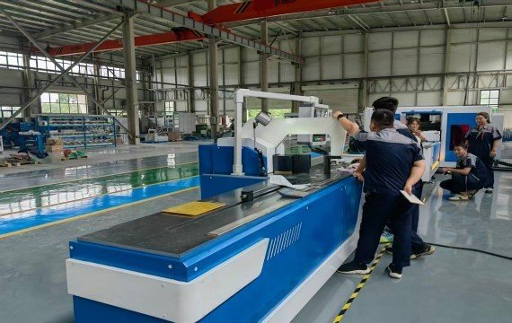
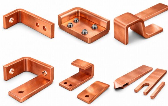
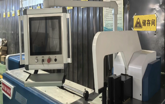
A busbar bending machine forms copper or aluminum conductors into the drawing-specific geometries required inside switchgear, electrical cabinets and power-distribution equipment. The approved electrical and mechanical design should define the conductor material, width × thickness, connection positions, insulation clearances and finished geometry. The bending process should reproduce that approved design rather than determine the electrical conductor section or cabinet layout.
This guide explains which busbar bending requirements should be confirmed, how springback and tooling interference affect the finished part, and how switchgear manufacturers should verify a bending machine through representative sample processing and factory acceptance testing.
Quick Answer
A busbar bending machine is used to produce flat bends, edge bends, offsets, U-bends, Z-bends and other approved geometries required for connections between circuit breakers, terminals, switches, insulating supports and cabinet structures.
The machine should be selected according to:
| Buyer Input | What Must Be Confirmed |
|---|---|
| Material | Copper grade or aluminum alloy and temper |
| Busbar Section | Common and maximum width × thickness |
| Raw Material | Common and maximum raw-bar length |
| Bend Direction | Flat bending, edge bending or another approved geometry |
| Finished Angle | Required angle after the workpiece is released |
| Inside Radius | Required finished internal bend radius |
| Bend Line | Position measured from the approved datum |
| Short Leg | Minimum finished flange or connection length |
| Bend Sequence | Approved order for multiple bends |
| Existing Features | Holes, slots and previously completed bends |
| Surface | Scratch, indentation, plating or coating limits |
| Tolerances | Angle, bend-line and overall dimensional limits |
| Production | Batch quantity, change frequency and conforming output |
| Acceptance | Sample-processing and FAT requirements |
What Does Busbar Bending Do in Switchgear Manufacturing?
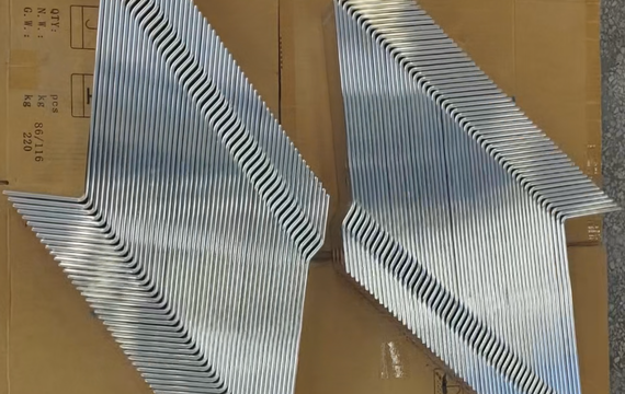
Busbar bending converts a flat conductor into the geometry required to connect electrical components and fit within the approved cabinet structure.
| Switchgear Requirement | Bending Purpose | Finished-Part Verification |
| Connections at Different Heights | Produces a vertical or offset transition | Offset height, released angle and overall dimensions |
| Breaker or Terminal Connections | Aligns the busbar with the connection surface | Flange length, hole position and assembly fit |
| Routing Around Components | Forms the conductor around approved devices or supports | Bend-line position, clearance and finished envelope |
| Phase Arrangement | Positions each phase conductor according to the drawing | Geometry, identification and phase spacing |
| Insulating Supports | Aligns the conductor with mounting and support positions | Bend location, hole location and support fit |
| Compact Cabinet Layout | Produces drawing-controlled profiles in limited space | Overall dimensions and interference inspection |
The bending machine supports mechanical fabrication. It does not independently determine current capacity, insulation clearance, phase spacing or the cabinet arrangement.
What Should Be Confirmed Before Bending?
| Drawing or Process Item | What to Confirm |
| Drawing Identity | Drawing number, revision, approval and part number |
| Material | Copper grade or aluminum alloy and temper |
| Width × Thickness | Actual conductor section |
| Raw Length | Supplied or approved pre-cut length |
| Datum | Approved reference end and longitudinal edge |
| Bend Direction | Flat, edge, offset or drawing-specific geometry |
| Finished Angle | Required released angle |
| Inside Radius | Required finished internal radius |
| Bend-Line Position | Distance from the approved datum |
| Short-Leg Length | Minimum finished flange or connection length |
| Bend Sequence | Order required for parts with several bends |
| Holes and Slots | Position relative to bend lines and tooling-contact areas |
| Existing Bends | Clearance required for later operations |
| Surface Requirements | Scratch, indentation, plating or coating limits |
| Finished Tolerances | Angle, bend-line and overall dimensional limits |
| Inspection Method | Instruments, sampling and acceptance criteria |
The supplier should review the complete drawing rather than only the maximum material width and thickness.
Which Busbar Bend Types Are Used in Switchgear?
| Bend Type | Typical Application | Critical Buyer Check |
| Flat Bend | Changes direction across the wide face | Angle, radius, short leg and surface |
| Edge Bend | Changes direction across the narrow edge | Material condition, force, tooling, twist and cracking |
| Offset Bend | Moves the conductor to another plane | Offset height, bend spacing and total dimensions |
| U-Bend | Produces a return or parallel section | Internal clearance, bend sequence and tool access |
| Z-Bend | Produces two opposing bends | Bend spacing, accumulated dimensions and interference |
| Double-End Bend | Forms two ends of a repeated conductor | Head spacing, support and total finished length |
| Customized Profile | Produces a drawing-specific geometry | Custom tooling, machine clearance and FAT sample |
A machine description that lists flat bending, edge bending or offset bending does not prove that every drawing can be processed.
How Does Bending Affect Switchgear Assembly?
| Finished-Part Problem | Possible Assembly Effect | Required Verification |
| Incorrect Released Angle | Connection surface does not align with the terminal | Measure the released finished angle |
| Incorrect Bend Line | Flange or connection position is displaced | Measure from the approved datum |
| Incorrect Short Leg | Connection length is insufficient or excessive | Measure the finished flange |
| Incorrect Inside Radius | Finished geometry does not match the drawing | Inspect the internal radius |
| Overall-Dimension Error | Part interferes with cabinet components | Measure the complete finished envelope |
| Twist or Torsion | Connection surfaces do not sit flat | Inspect flatness and torsional condition |
| Surface Indentation | Visible or contact surfaces are damaged | Inspect tooling-contact areas |
| Bend Cracking | Material is damaged during forming | Inspect both sides of the bend |
| Combined Hole and Bend Error | Holes do not align after bending | Measure holes and bends from approved datums |
An assembly problem should be traced to measured finished-part characteristics.
Do not automatically attribute every assembly problem to the bending machine. Possible causes may include the drawing, material, datum, tooling, bend sequence, alignment, support, springback correction or inspection method.
Why Must Springback Be Verified?
The programmed value, controller display, bending-stroke position and angle under force are not automatically the finished bend angle.
After the conductor is released from the tooling, the material may partially recover. This is commonly called springback.
The released angle may change with:
| Variable | Why It Matters |
| Material Grade or Alloy | Different materials respond differently during forming |
| Temper | Material condition affects deformation and recovery |
| Width × Thickness | Changes the force and forming condition |
| Bend Direction | Flat and edge bends behave differently |
| Inside Radius | Influences material deformation |
| Tooling | Defines contact, radius and forming geometry |
| Initial Alignment | Affects bend position and part symmetry |
| Workpiece Support | Long conductors may move or rotate |
| Correction Setting | Changes the forming position or stroke |
| Previous Bends | May affect alignment and tooling access |
The released workpiece should be measured after removal from the tooling.
When material, temper, thickness, bend direction, tooling or bend geometry changes, the approved correction value should be checked again.
How Should Tooling and Interference Be Reviewed?
| Tooling or Interference Item | What the Buyer Should Confirm |
| Standard Tooling | Tool codes, quantities, radii and included applications |
| Optional Tooling | Price, application and delivery time |
| Customized Tooling | Drawing approval, design responsibility and testing method |
| Tool Radius | Compatibility with the required inside bend radius |
| Flat-Bending Tool | Material and width × thickness range |
| Edge-Bending Tool | Applicable section, clearance and support |
| Minimum Short Leg | Smallest practical flange supported by the tooling |
| Hole-to-Bend Distance | Whether holes enter the tooling-contact area |
| Previously Formed Section | Whether it interferes with the tool, table or frame |
| Workpiece Rotation | Space required for long and multi-bend parts |
| Surface Protection | Permitted tool marks and protective method |
| Tool Maintenance | Inspection, repair and replacement requirements |
Do not accept “bending tooling included” without an itemized tooling list.
Which Machine Configuration Fits the Production Requirement?
| Production Requirement | Starting Configuration | Critical Buyer Check |
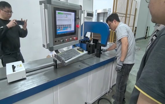
| Customized and Low-Volume Parts | Hydraulic busbar bending machine | Tooling, positioning method and first-part setup |
| Recurring Bend Positions | CNC or servo-assisted bending machine | Controlled axes, positioning range and program recall |
| Repeated Double-End Parts | Double-head busbar bending machine | Head spacing, support and finished dimensions |
| Punching, Shearing and Bending in One Area | 3-in-1 busbar processing machine | Independent capacity of each station |
| Complex Repeated Bending | Dedicated programmable busbar bender | Tooling interference, springback and variation |
| Several Operations Run in Parallel | Separate dedicated machines | Staffing, transfers and line balance |
This table is a starting point rather than a final model recommendation.
Final machine selection should be based on representative drawings, operation-specific capacity, tooling, remaining manual tasks and sample-processing results.
How Should Finished Busbars Be Inspected?
| Inspection Item | What to Record |
| Part Identity | Project, cabinet, phase and part number |
| Drawing | Number and approved revision |
| Material | Grade or alloy, temper and width × thickness |
| Bend Direction | Flat, edge, offset or approved special geometry |
| Released Angle | Actual angle after removal from tooling |
| Bend-Line Position | Actual distance from the approved datum |
| Inside Radius | Finished internal bend radius |
| Short-Leg Length | Finished flange or connection dimension |
| Overall Dimensions | Complete finished-part envelope |
| Twist or Deformation | Flatness and torsional condition |
| Cracking | Visible damage around the bend |
| Surface | Indentation, scratches or coating damage |
| Hole and Slot Position | Position after bending |
| Assembly Interface | Fit with terminals, breakers and supports where required |
| Status | Accepted, reworked, rejected or held |
Controller resolution, axis-positioning accuracy and finished-part tolerance should be recorded separately. The controller display should not replace inspection of the released workpiece.
Frequently Asked Questions
Why Are Busbar Bending Machines Used in Switchgear Manufacturing?
They form copper or aluminum conductors into the approved geometries required to connect devices and fit within the switchgear structure. The finished part should meet the drawing-defined angle, bend line, radius and overall dimensions.
What Is the Difference Between Flat and Edge Busbar Bending?
Flat bending forms the conductor across its wide face. Edge bending forms the conductor across its narrower edge. The two operations require different tooling, force, support and interference checks.
Why Does a Copper Busbar Spring Back After Bending?
After the forming force is removed, the material may partially recover. The released result depends on material, temper, section, bend direction, radius, tooling, alignment and correction settings.
Does CNC Guarantee the Finished Bend Angle?
No. CNC or servo control may manage a defined position, stroke or correction value. The finished released angle also depends on material, tooling, alignment, support and springback.
Can a 3-in-1 Busbar Machine Bend Switchgear Busbars?
Yes, where the bending station, tooling and workpiece access match the drawing. Confirm the bending capacity separately from the punching and shearing capacities.
Final Thoughts
A bending machine is a combined system of structure, hydraulics, and machining.The real differences lie in its manufacturing. The same configuration will yield different results in different factories. If you have any questions in this regard, please feel free to contact Fenghua.