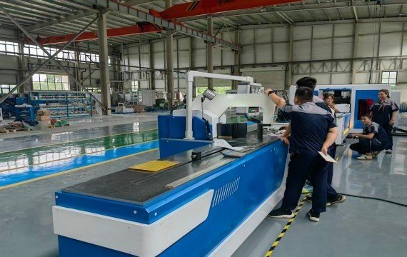
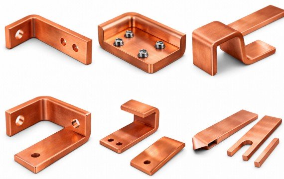
Coil winding is the controlled process of placing insulated electrical conductor onto a mandrel, bobbin, core or former to produce a coil with an approved number of turns, direction, dimensions, layer structure and lead position.
This guide explains the coil winding process, the machine systems that buyers should compare and the information required for sample winding and factory acceptance testing.
Quick Answer: What Is Coil Winding?
Coil winding is the process of placing insulated copper or aluminum conductor onto an approved mandrel, bobbin, core or former to produce a coil with the required turns, winding direction, dimensions, layers, insulation and lead positions.
Where Coil Winding Is Used in Industrial Production
| Application | Typical Coil Requirement | Machine Selection Focus |
|---|---|---|
| Transformer Wire Windings | Approved turns, winding direction, coil dimensions, layers, insulation and leads | Winding load, torque, turn counting, tension, traverse and mandrel |
| Transformer Foil Windings | Copper or aluminum foil with interlayer insulation | Decoiling, foil tension, edge alignment, insulation feeding and joining |
| Reactors and Inductors | Drawing-controlled conductor placement and coil geometry | Conductor range, mandrel, tension and repeatable turn count |
| Motor or Generator Coils | Application-specific winding geometry and conductor placement | Machine type, tooling and stator or rotor process |
| Solenoids and Electrical Coils | Defined turns, resistance, dimensions and lead position | Wire range, winding speed, counter and fixture |
The application name alone does not define the correct machine. Transformer wire coils, foil coils, motor stators and toroidal coils may require different machine structures, tooling and automation.
Transformer Making
The winding structure determines voltage. Deviations in the winding can lead to an abnormal temperature rise.
Fluctuations in interlayer spacing can cause overload operation, increasing rework and testing. Stable winding locks in the interlayer structure, reducing testing rework.
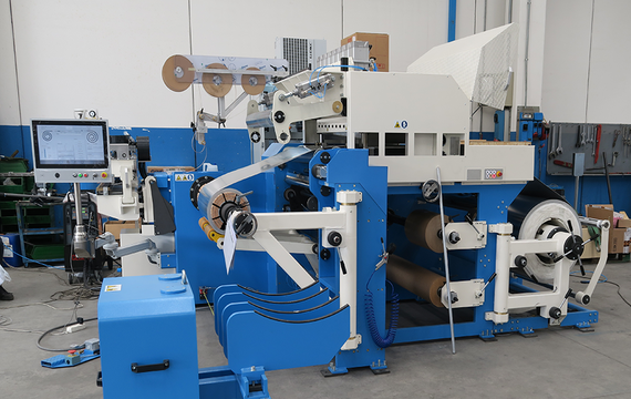
Motor Stator Production
Coils determine torque and operation. You use the stator winding structure to control the magnetic field distribution. Uneven winding can cause vibration and noise.
These problems can lead to a poor overall machine reputation. A stable winding control system can reduce operator errors, decrease fluctuations in later stages, and improve your yield rate.
Industrial Electrical Equipment
Power a controllable coil structure. You need to adjust the winding parameters according to different electrical loads and match the magnetic field with the current.
High-frequency current causes leading to issues during winding. Programmable winding structural deviations and support switching specifications, thus reducing your hidden costs.
Which Process Variables Affect Coil Winding Quality?
| Process Variable | What Should Be Defined | What Should Be Verified |
|---|---|---|
| Conductor | Copper or aluminum, round, rectangular, strip or foil | Material, dimensions, insulation and surface |
| Mandrel | Shape, dimensions, connection and support | Fit, alignment, rigidity and removal method |
| Turn Count | Required turns and counting direction | Forward, reverse and power-off-memory test |
| Winding Direction | Clockwise or counterclockwise from an approved reference | Actual finished direction |
| Speed | Operating speed by conductor, load and coil geometry | Vibration, stopping and finished-coil result |
| Torque | Required torque under the approved winding load | Actual load test |
| Tension | Required method and adjustable range | Conductor condition and coil compactness |
| Traverse or Guiding | Pitch, travel and guide position | Conductor arrangement and edge position |
| Layer Structure | Turns per layer, layer quantity and insulation | Actual layer arrangement |
| Lead Position | Starting and finishing lead location | Finished lead dimensions and direction |
| Coil Dimensions | Internal diameter, external diameter, height and overall geometry | Finished measured values |
| Surface Condition | Permitted marks, insulation damage and conductor deformation | Visual and dimensional inspection |
Tension Stability
Winding tension should be selected according to the conductor material, cross-section, insulation, coil geometry, mandrel and operating speed. Excessive tension may stretch, deform or damage the conductor and insulation. Insufficient tension may produce a loose or unstable winding. The quotation should therefore identify the tension method, adjustable range, feedback method and how tension performance will be checked during sample winding.
Do not assume that every machine includes servo or closed-loop tension control. Confirm the actual supplied configuration.
Layer Alignment
Layer and conductor alignment should conform to the approved winding drawing and process specification. Depending on the coil type, buyers should inspect conductor spacing, edge position, layer transition, insulation placement, coil height, telescoping, crossed turns and lead position.
Automatic traversing may help control conductor position, but it does not by itself prove finished-coil conformity. Alignment also depends on the conductor, guide setup, mandrel, tension, operating speed and initial threading.
Repeatabal Production
Repeatable production should be evaluated by comparing finished coils produced under the same approved material, mandrel, tooling and winding settings. For an agreed sample batch, inspect the first, middle and final coils. Compare turn count, winding direction, internal and external dimensions, coil height, layer arrangement, insulation position, lead position and surface condition.
Program storage and automatic turn counting may reduce repeated setup work, but loading, threading, insulation placement, lead preparation, coil removal and final inspection may remain manual.
Machine Selection Logic for Buyers
Coil winding equipment product. Different equipment strengths and mismatched selection can amplify wiring errors. You need to choose a product. Below is a breakdown of the paths for different equipment.
| Configuration | Typical Included Functions | Suitable Starting Point | Buyer Must Confirm |
|---|---|---|---|
| Manual or Hand-Operated Winder | Manual rotation or basic turn counting | Repair, prototypes and low-volume simple coils | Load, mandrel, operator effort and finished results |
| Motorized Winder With Counter | Powered spindle, speed adjustment and turn counter | Small and mixed production | Speed range, braking, reverse winding and counter functions |
| Variable-Frequency Reversible Winder | VFD speed control, forward and reverse winding, braking and counting | Transformer coils requiring controlled spindle operation | Load, torque, stopping, mandrel support and manual tasks |
| Programmable Wire-Traverse Winder | Programmed spindle and wire-guide coordination where included | Repeated layered wire coils | Controlled axes, guide travel, pitch, tension and program recall |
| Transformer Foil Winder | Foil decoiling, insulation feeding and winding systems | LV copper or aluminum foil coils | Foil range, reel load, tension, edge alignment and joining |
| Customized Heavy-Load Winder | Project-specific spindle, mandrel, supports and drive | Large or heavy transformer coils | Winding load, torque, speed under load, layout and FAT |
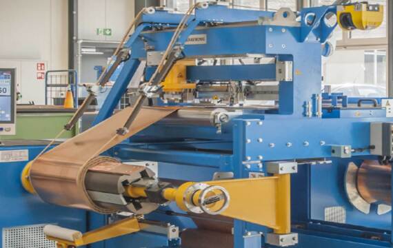
Which Machine Systems Should Buyers Confirm?
The engineering structure of your coil winding equipment determines your production. The challenges you face include motion control, wire feeding, and control logic. Poorly designed wire breakage during high-speed production. Below is an introduction to these aspects.
Spindle, Drive and Braking System
The spindle and drive system should provide the required winding direction, operating speed, torque and stopping performance for the approved mandrel and winding load.
Confirm:
- Maximum winding load
- Spindle and mandrel connection
- Effective spindle length
- Supported mandrel diameter
- Operating-speed range
- Torque requirement
- Forward and reverse winding
- Braking and self-locking
- Tailstock or secondary support
- Vibration and shaft movement under load
Conductor Payoff, Tension and Guiding
The conductor-handling system may include a payoff stand, reel brake, straightening, tension control, guide rollers and manual or automatic traversing. Confirm the conductor material, shape, cross-section, reel dimensions, reel weight, insulation, minimum bend condition, guide travel and threading method. Copper and aluminum compatibility should be confirmed separately because their dimensions, mechanical behavior, insulation and required tension settings may differ.
Turn Counting and Control Functions
The quotation should identify the exact control functions rather than using only the terms CNC or automatic.
Confirm:
- Turn-counting method
- Forward and reverse counting
- Display resolution
- Power-off memory
- Program storage
- Speed setting
- Traverse-axis control
- Tension feedback
- Alarm functions
- Data storage
- Program backup and restoration
A controller value is not a substitute for finished-coil inspection.
What Should Be Confirmed for a Customized Winding Project?
| Project Item | Buyer Should Provide | Supplier Should Confirm |
|---|---|---|
| Coil Drawing | Internal diameter, external diameter, height, turns and layers | Machine, mandrel and guide compatibility |
| Conductor | Material, shape, dimensions and insulation | Payoff, tension, guide and torque suitability |
| Winding Load | Mandrel, conductor and finished-coil weight | Approved load and FAT method |
| Mandrel | Drawing, material, connection and removal method | Spindle interface, support and tooling |
| Winding Process | Direction, speed, layer sequence, insulation and leads | Included control and manual operations |
| Production Requirement | Batch size, change frequency and required output | Cycle boundary, operator tasks and changeover |
| Workshop Layout | Loading side, operator side, available space and lifting method | Machine outline, clearances and maintenance access |
| Electrical Supply | Voltage, frequency and site conditions | Approved electrical configuration |
| Safety | Operator access and customer requirements | Guards, emergency stops, braking and interlocks |
| Documentation | Language and required records | Manuals, drawings, component list and backups |
| Acceptance | Sample quantity, characteristics and tolerances | Sample-winding plan and FAT report |
Electrical Standard Adaptation
Exporting your equipment voltage, coils, and control has different standards, and equipment that doesn’t support localization will prevent production.
You’ll encounter voltage mismatches and control system response delays, increasing commissioning time and costs. Customizable electrical systems allow equipment to adapt to different markets, reducing on-site lowering your commissioning risks.
Production Line Integration
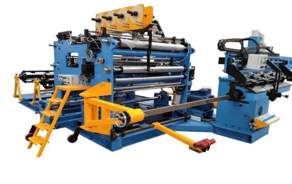
Coil winding equipment includes feeding, winding, inspection, and unloading.Incompatible equipment interfaces will result in secondary material and manual handling. A well-designed production line supports the integration of your equipment into transformers and lowers production line adjustment costs.
Long-Term Operation
Importers prioritize smooth equipment operation; you need low maintenance. Poorly designed equipment results in frequent downtime.
High-intensity production processes cause parts to wear down, impacting equipment lifespan. Specially designed winding equipment reduces costs in your production.
How Should Sample Coil Winding and FAT Be Verified?
| FAT Item | What to Record |
|---|---|
| Machine Identification | Model, serial number and approved configuration |
| Coil Drawing | Drawing number, revision and critical characteristics |
| Conductor | Material, dimensions, insulation and batch |
| Mandrel | Drawing, dimensions, connection and test condition |
| Winding Load | Mandrel, conductor and finished load |
| Machine Settings | Speed, direction, tension, traverse and correction values |
| Turn Counter | Forward count, reverse count and power-off memory |
| Finished Turns | Required and verified turn count |
| Coil Dimensions | Internal diameter, external diameter, height and overall geometry |
| Layer Structure | Turns per layer, layer count and transitions |
| Conductor Arrangement | Alignment, spacing, crossed turns and edge position |
| Insulation | Material, location, overlap and visible damage |
| Leads | Start and finish position, length and direction |
| Surface | Scratches, conductor deformation and insulation damage |
| Repeated Coils | First, middle and final results |
| Operator Tasks | Loading, threading, insulation, leads, removal and inspection |
| Safety | Emergency stops, guards, braking and restart behavior |
| Documents | Manuals, drawings, parameters and software backups |
| Open Issues | Deviation, corrective action and approval status |
FAQ
What industries primarily use coil winding equipment?
Coil winding is used in power equipment manufacturing, industrial automation, new energy systems, and electrical component production.
What materials coil winding?
Industrial winding primarily uses copper and aluminum wire. Copper wire is used in high-conductivity applications, while aluminum wire is used for cost control or lightweight design.
How does coil winding affect equipment energy consumption?
Coil structure affects electromagnetic losses. An unreasonable structural design increases resistance losses, causing a decline in motor or transformer performance.
What should be considered when upgrading older winding equipment?
Upgrading requires considering capacity expansion needs and the changes in product structure.
Final Thoughts
The winding process determines the winding machine system, which defines production and export. Automation is a production requirement. If you have any questions, please contact Fenghua.We will provide you with excellent service.