Busbar Connector Punching and Shearing Solutions
On this page, a busbar connector means a conductive connector or joint bar defined by its material, grade or temper, thickness, width, finished length and hole or slot pattern. If your part is a non-conductive cover, protection plate or pressure plate, request a separate process review because the required machine and cutting method may differ.
Nominal thickness and width alone are not enough for machine selection. A useful technical quotation should connect the actual drawing to a confirmed machine model, tooling list, positioning method, electrical configuration and acceptance test.
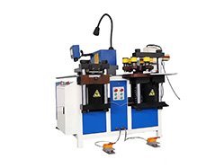
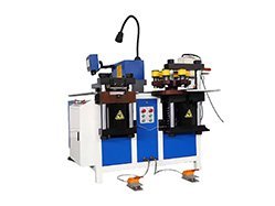
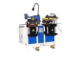
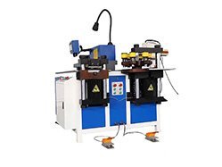
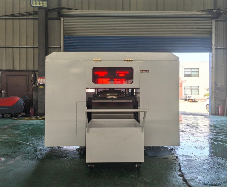
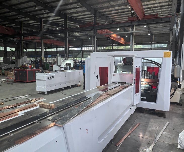
The available configuration uses a six-axis servo CNC system for busbar connector punching and shearing. Axis functions, positioning method and material-specific limits are confirmed during the drawing review. The controlled-axis definitions, material-specific limits, software functions and positioning method must be stated separately in the technical quotation.
Available Machine and Application Configurations
The configurations below represent different machine or application routes. Final model selection follows drawing and material review. A configuration should not be treated as a separate product model unless it has its own model number, technical sheet, machine image and valid product URL.
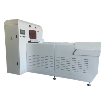
For dedicated connector or joint-bar punching and shearing projects. Confirm the current model, material-specific capacity, tooling, positioning method, hole or slot range and acceptance criteria before quotation.
The supplied technical sheet identifies a six-axis servo CNC machine with punching and shearing functions. The controlled-axis roles and operation-specific limits must be confirmed for the quoted configuration.
Copper and aluminum applications require separate review by material grade or temper, thickness, width, tool clearance and drawing requirements. Material compatibility should not be inferred from nominal dimensions alone.
For round holes, slots or non-standard layouts, submit the drawing, required tolerances and output target. The quotation should identify the included dies, setup method, first-piece test and spare-tooling scope.
How to Select the Right Busbar Machine for Your Project
| Production Requirement | Recommended Machine Type | Suitable Applications | Key Selection Checks |
|---|---|---|---|
| Occasional cutting, punching or simple bending | Hydraulic Busbar Machine | Repair workshops, prototype production and low-volume busbar processing | Maximum busbar width × thickness, available tooling, positioning method and operator requirements |
| Punching, cutting and bending on one machine | 3-in-1 Busbar Processing Machine | Switchgear, distribution cabinet, transformer and electrical panel production | Separate capacity for each station, tooling list, station layout and changeover time |
| Repeated drawings and multiple specifications | CNC Busbar Processing Machine | Medium- and high-volume production requiring programmed processing | Positioning accuracy, repeatability, program storage, feeding method and supported part specifications |
| Connector plates with repeated holes and controlled cut lengths | Busbar Connector Punching and Shearing Machine | Busduct connectors, joint bars and electrical connection plates | Material grade, width × thickness, hole or slot layout, finished length, included tooling and FAT criteria |
| Flat, vertical or customized bending | Dedicated Busbar Bending Machine | Switchgear conductors, transformer connections and customized busbar assemblies | Bending direction, maximum capacity, angle control, tooling radius and springback compensation |
The correct machine should be selected according to the finished busbar drawing, required processes, material specification, production volume and acceptance criteria—not only the advertised hydraulic force or maximum capacity.
What to Confirm Before Selecting a Busbar Connector Machine

Confirm the material, grade or temper, surface condition, raw length, finished length, thickness and width. Maximum values must be evaluated separately for punching and shearing.

Provide the hole or slot shape, finished size, center-to-center pitch, hole-to-edge distance, quantity and required tolerances. The included dies and tooling reach should be listed in the quotation.

Confirm the finished cut length, cut-length tolerance, squareness, burr requirement, surface requirement and allowable deformation.

Provide batch size, daily output, changeover frequency, loading method, and destination electrical supply. Define the first-piece and FAT measurement plan before production.
Drawing-Based Machine and Tooling Selection
Send an approved drawing together with the material specification, raw-stock dimensions, required hole or slot pattern, cut length, tolerances and expected output. Model selection should then confirm the machine configuration, included tooling, positioning method, electrical supply, operator scope and acceptance items.
For non-standard parts, request a processed sample made from the specified material before final acceptance. The sample report should identify the drawing revision, material, tooling, measuring instruments, and measured results.
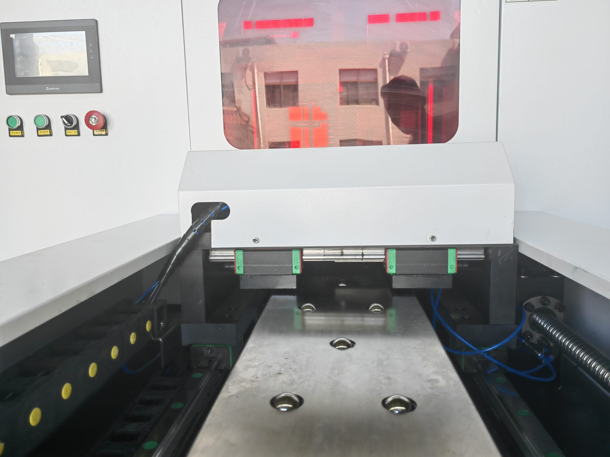
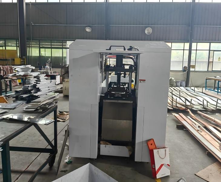
How Punching and Shearing Quality Should Be Verified
Punching and shearing quality should be evaluated from measured finished parts rather than general claims such as “high precision” or “stable accuracy.” Agree on the inspection method before the machine is accepted.
Relevant measurements may include finished hole diameter, hole-center position, center-to-center pitch, hole-to-edge distance, cut length, cut squareness, burr height, flatness and visible surface damage. The applicable items and tolerances must come from the approved customer drawing.
For recurring parts, approve a first article before batch production and retain the drawing revision, machine setup, tooling and measurement record.
How to Estimate Production Output and Changeover Time
Actual output depends on the number of holes, hole types, tool changes, feed length, loading and unloading method, shearing sequence, first-piece inspection and operator workflow. The current source sheet does not provide a verified processing speed or complete cycle time.
For a reliable comparison, request a timed sample using your actual drawing and material. Record loading, setup, punching, shearing, unloading and inspection time separately. Do not publish fixed percentage improvements unless the comparison method and test conditions are documented.
How to Compare Busbar Connector Machine Manufacturers in China
There is no universally recognized official “Top 10” ranking for busbar machine manufacturers in China. Supplier-published lists should be used as comparison guides rather than awards.
When comparing manufacturers, verify the current machine model, connector or joint-bar samples, material-specific capacity, punching and shearing functions, controlled-axis definitions, tooling, positioning method, sample measurement report, electrical configuration, FAT scope, documentation, spare parts and after-sales terms.
A supplier of general busbar machines should not automatically be treated as a specialist in busbar connector or joint-bar processing without a relevant model, sample and acceptance record.
Processing Multiple Busbar Connector Specifications
The source sheet confirms a CNC configuration but does not define drawing import, automatic material recognition, program storage or parameter-recall functions.
For factories processing multiple part numbers, the technical quotation should state how programs and setup values are created, stored, recalled and revised; how tooling changes are performed; and how the first part is checked after each changeover.
Material, tooling and drawing revision must be verified before a saved setup is reused.
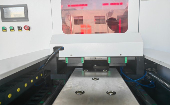
Record the approved drawing number, revision, material and tooling with each recurring production setup.
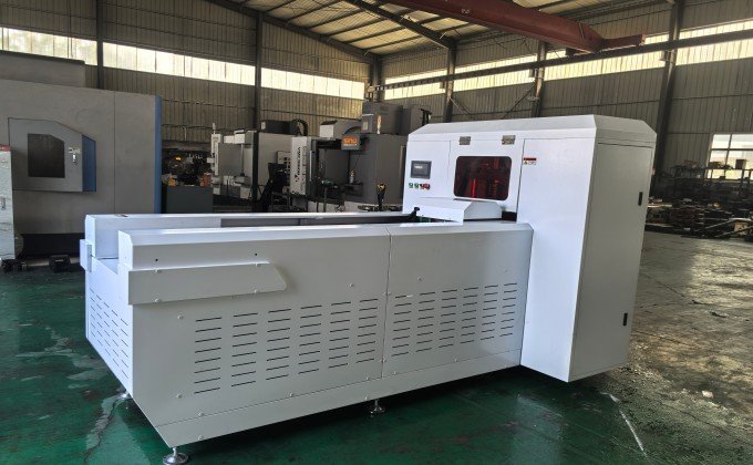
After changing specifications or tooling, process and inspect a first article before starting the batch.
Provide the workpiece drawing, material, grade or temper, surface condition, raw and finished dimensions, hole or slot layout, cut length, required tolerances, batch size, output target and destination electrical supply. These details are required to confirm the machine configuration and tooling.
Compatibility cannot be confirmed from the material name alone. Copper and aluminum should be reviewed separately according to grade or temper, thickness, width, tooling clearance, punching requirement and shearing requirement. Send both material specifications and drawings for review.
The supplied technical sheet lists a six-axis servo CNC configuration with maximum source values of 16 mm thickness and 200 mm width. The sheet does not define the applicable material grade or whether these values apply equally to punching and shearing. Confirm the actual workpiece before quotation.
Hole-position accuracy should be confirmed through a processed sample and measured against the approved drawing because the current configuration does not publish a standard accuracy value.Hole-center position, pitch, edge distance, finished diameter and related tolerances should be measured from a processed sample against the approved drawing.
The published standard voltage is 380 V. Confirm the required frequency, phase and local electrical standard before production. Confirm the destination voltage, frequency, phase, installed power and local electrical requirements before production.
Operators require training for tooling installation, setup, parameter verification, first-piece inspection, safe operation and routine maintenance. The exact control functions and training scope should be recorded in the quotation.
The quotation should identify the model, machine functions, material-specific capacity, controlled-axis definitions, included dies, positioning method, electrical configuration, component scope, sample test, FAT items, documentation, installation, training, warranty and spare-parts terms.
Remote support, commissioning, operator training, spare parts, response times and on-site service costs should be stated in the quotation and contract. Do not rely on general promises such as “24-hour problem solving” unless they are contractually defined.