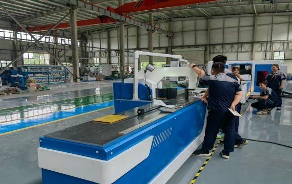
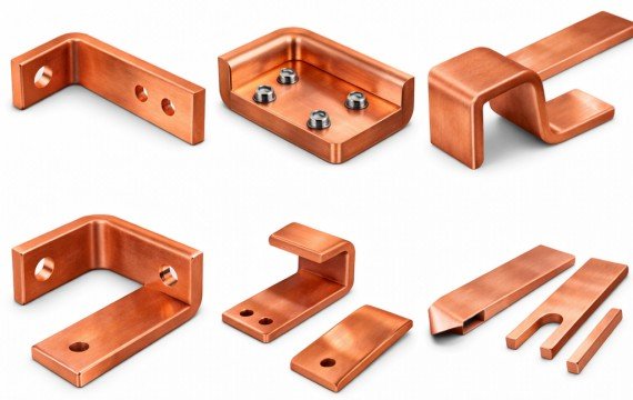
Transformer coil winding is the controlled process of placing insulated copper or aluminum conductor onto an approved mandrel, former, bobbin or winding tool according to a released coil drawing and process specification. The complete process includes drawing review, material verification, mandrel installation, conductor payoff, tension and guiding setup, turn counting, layer or section formation, insulation placement, lead preparation, coil removal, inspection and production records.
This guide explains a practical industrial workflow for wire-wound transformer coils. Foil windings require a different process involving foil decoiling, edge alignment, insulation feeding and conductor joining.
Quick Answer: How Is a Transformer Coil Wound?
A transformer coil is normally produced through the following steps:
- Review the approved coil drawing and process sheet.
- Verify the conductor, insulation and supporting materials.
- Inspect, install and align the mandrel or former.
- Load the conductor reel and configure the payoff.
- Set the winding direction, speed, counter, tension and guiding method.
- Complete trial turns and approve the first layer or section.
The winding machine should support the approved process. It does not independently determine transformer efficiency, temperature rise, insulation performance or final electrical conformity.
What Defines an Approved Transformer Coil?
| Coil Requirement | What Should Be Defined |
|---|---|
| Drawing Identity | Drawing number, revision and approval |
| Application | HV, LV, regulating, reactor or another winding |
| Conductor | Copper or aluminum, round, rectangular, strip or another approved form |
| Conductor Size | Diameter or width × thickness |
| Conductor Insulation | Material, thickness and permitted surface condition |
| Coil Geometry | Internal diameter, external diameter, height and axial dimensions |
| Turn Count | Total turns and turns per layer, section or disc |
| Winding Direction | Clockwise or counterclockwise from an approved reference |
| Winding Structure | Layer, disc, helical, sectioned or another approved design |
| Insulation Structure | Layer insulation, end insulation and barriers |
| Cooling Structure | Ducts, strips or spacers where specified |
| Leads and Taps | Starting lead, finishing lead and tapping positions |
| Mandrel | Dimensions, connection, support and removal method |
| Tolerances | Finished dimensional and process limits |
Production should not begin when the drawing revision, conductor, winding direction, turn count, insulation structure or lead positions remain unclear.
What Materials, Tooling and Equipment Are Required?
| Category | What to Confirm Before Winding |
| Conductor | Material, dimensions, insulation, reel identity and surface |
| Layer Insulation | Material, thickness, width, overlap and orientation |
| End Insulation | Rings, blocks, washers or barriers where specified |
| Cooling Components | Spacers, strips or ducts where specified |
| Mandrel or Former | Drawing, dimensions, connection, rigidity and release method |
| Payoff Equipment | Reel dimensions, reel weight, brake and loading method |
| Tension System | Type, adjustment range and supplied configuration |
| Guiding System | Manual guide, mechanical guide or programmable traverse |
| Turn Counter | Range, forward and reverse logic and power-off memory |
| Measuring Equipment | Approved dimensional instruments, templates and gauges |
| Handling Equipment | Crane, hoist, trolley or lifting fixture where required |
| Documentation | Drawing, process sheet, inspection plan and batch traveler |
The machine configuration should match the approved winding load, mandrel, conductor, speed, torque, tension, guiding method, insulation process and operator tasks.
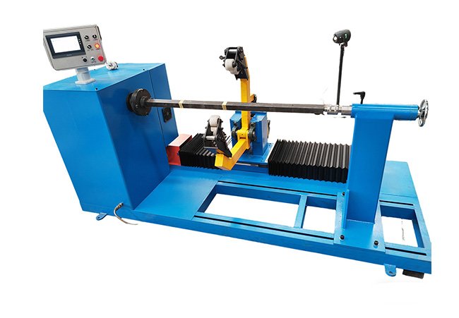
Industrial Coil Winding Process Steps
You need to determine the wire specifications and secure the iron core to prevent displacement that it isinter-layer structural stability.
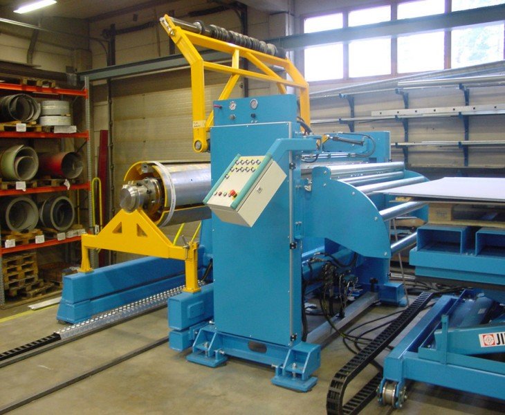
Preliminary Preparation
You must determine the wire type, diameter, and insulation class. Before winding, the core must be precisely secured to prevent structural shifting during operation; failure to do winding the finished product.
Winding Control
During the winding process, you must control speed and ensure a uniform and consistent coil structure, avoiding uneven tightness or interlayer misalignment. Insulating materials should be inserted for product safety and to improve long-term operational stability.
Inspection of Finished Products
Once the winding process is complete, the coils require finishing to ensure they meet specifications. Before the product is released for shipment, its dimensions, structure, and electrical performance must be verified to ensure the final product complies with manufacturing standards.
Common Transformer Coil Winding Problems
| Observed Problem | Possible Cause | Required Verification |
| Uneven Conductor Arrangement | Guide setup, initial alignment, tension or operator correction | Inspect spacing, edge position and crossed turns |
| Loose Winding | Insufficient tension, mandrel movement or conductor handling | Review tension method and finished dimensions |
| Conductor Deformation | Excessive tension, small bend condition or poor guiding | Inspect conductor and insulation |
| Damaged Insulation | Guide contact, tension, conductor edges or handling | Inspect the damage location and process step |
| Incorrect Turn Count | Counter setup, reverse logic, interruption or manual recording | Verify against the approved process sheet |
| Incorrect Winding Direction | Setup or drawing-reference error | Confirm direction from the approved reference |
| Incorrect Coil Height | Layer spacing, conductor arrangement or insulation placement | Measure at defined process stages |
| Telescoping or Layer Shift | Mandrel alignment, guide position, tension or speed | Inspect axial displacement |
| Incorrect Lead Position | Starting datum or process-sequence error | Measure lead length, direction and location |
| Coil Cannot Be Removed | Mandrel design, release allowance or deformation | Review mandrel drawing and removal method |
Do not automatically attribute every winding problem to the machine.
Possible causes may include the drawing, conductor, insulation, mandrel, payoff, guide, tension, speed, process sequence, operator action or inspection method.
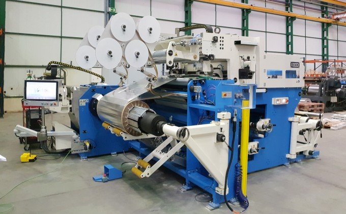
Optimized Process Flow
Consistent tension is essential during the winding process to ensure quality; automatic tension control enhances this stability. Fixed parameters guarantee consistency across product batches. Using automated equipment is recommended, as it minimizes human error and reduces the product defect rate.
| Control Point | Required Record |
|---|---|
| Approved Inputs | Drawing, material, mandrel and process revision |
| Machine Setup | Direction, speed, counter, tension and traverse |
| First-Layer Approval | Conductor position, spacing, insulation and dimensions |
| In-Process Checks | Layer, section, duct, tap and lead positions |
| Process Changes | Adjustment, interruption and corrective action |
| Finished-Coil Inspection | Turns, dimensions, arrangement, insulation, leads and surface |
| Production Status | Accepted, reworked, rejected or held |
Industrial Applications
| Transformer Application | Typical Winding Focus |
|---|---|
| Distribution Transformer | Repeated coil dimensions, leads, insulation and production records |
| Power Transformer | Heavy winding load, complex winding structure, insulation and mechanical support |
| Dry-Type Transformer | Approved conductor, solid insulation, dimensions and casting compatibility |
| Oil-Immersed Transformer | Conductor, paper insulation, cooling ducts, drying and assembly requirements |
| Reactor | Turn count, conductor arrangement, dimensions and application-specific structure |
The application name alone does not define the correct winding machine or process. Use the approved coil drawing, conductor, mandrel, insulation structure, winding load and acceptance requirements.
How Should the Transformer Winding Machine Be Verified During FAT?
| FAT Item | What to Verify | Required Evidence |
|---|---|---|
| Machine Identity | Model, serial number and approved configuration | Nameplate and configuration sheet |
| Coil Drawing | Number, revision and critical characteristics | Approved drawing |
| Conductor | Material, dimensions, insulation and batch | Material record |
| Mandrel | Dimensions, connection, support and removal | Approved drawing and photos |
| Winding Load | Mandrel, conductor and finished-coil load | Recorded test condition |
| Direction and Speed | Forward, reverse and operating range | Parameter record |
| Turn Counter | Forward, reverse and power-off memory | Known-turn test |
| Tension | Method, setting and actual conductor result | Process record |
| Guiding or Traverse | Travel, pitch and conductor position | Inspection result |
| Finished Coil | Turns, dimensions, structure, leads and surface | Measurement report |
| Repeated Samples | First, middle and final results | Comparison sheet |
| Operator Tasks | Loading, threading, insulation, leads and removal | Manual-task record |
| Safety | Braking, emergency stop, guards and restart behavior | Safety checklist |
| Documents | Manuals, drawings, parameters and backups | Document index |
| Open Issues | Deviations, corrective actions and approval | Signed issue list |
Each FAT item should include the test method, acceptance criterion, actual result, measuring instrument, pass-or-fail decision and corrective action. A short sample test verifies immediate winding capability under recorded conditions. It does not by itself prove long-term machine reliability or sustained process capability.
Frequently Asked Questions
Why Can Winding Results Vary When the Same Parameters Are Used?
The same controller settings do not guarantee identical finished coils.
Results may vary because of conductor batches, insulation thickness, reel condition, mandrel alignment, guide setup, actual tension, machine condition, process interruptions or operator actions.
Compare finished-coil measurements rather than only the stored parameters.
Is Faster Winding Speed Always Better?
No.
The appropriate speed depends on the winding load, conductor, payoff, tension method, guiding system, mandrel balance, insulation process and required finished-coil result.
Higher speed should be approved through representative winding and inspection.
Is a Transformer Coil Always Wound Directly on the Iron Core?
No.
Many transformer coils are wound on a mandrel, former, cylinder or winding tool and are later assembled with the transformer core.
The actual method depends on the approved transformer and winding design.
Are All Transformer Coils Suitable for Automatic Winding?
No.
The appropriate machine configuration depends on the coil dimensions, winding load, conductor, mandrel, insulation process, lead preparation, batch quantity and required operator tasks.
Automatic control may apply only to selected functions.
How Should Winding Tension Be Selected?
Tension should match the conductor material, cross-section, insulation, mandrel, coil geometry and operating speed.
The setting should be verified through trial winding and finished-coil inspection.
Why Is Inspection Required After Winding?
The machine display does not prove that the finished coil meets the approved drawing.
Inspect the turn count, winding direction, internal and external dimensions, coil height, winding structure, insulation, leads, taps, cooling components, surface condition and identification.
Final Thoughts
Transformer winding requires a controlled industrial process. We recommend using automated production processes. Please feel free to contact us if you require technical support or industrial winding solutions.