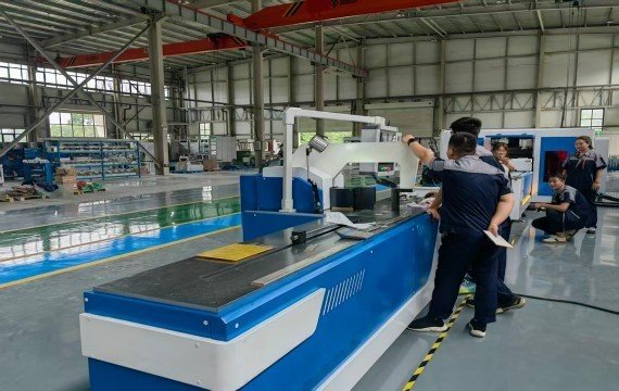
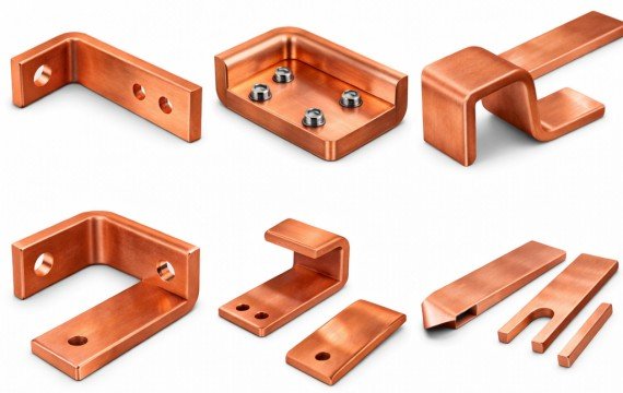
A busbar is a rigid electrical conductor used to collect and distribute current between incoming terminals, circuit breakers, switches and other components in electrical equipment. In switchgear and electrical cabinets, the approved electrical design determines the busbar material, conductor section, arrangement, insulation, clearances and connection requirements. The fabrication process then converts that design into parts with the required lengths, holes, slots, bends, surfaces and identification.
This guide explains what a busbar is, how it is prepared for cabinet assembly and when a busbar processing machine becomes useful. It focuses on fabricated conductors inside electrical equipment rather than complete busbar trunking or busway systems.
Quick Answer
A busbar is a rigid copper or aluminum conductor used to carry and distribute electrical current inside switchgear, electrical cabinets, transformers and other power equipment. The manufacturing process then uses approved drawings to shear, punch, bend, deburr, inspect and identify the finished busbar.
A busbar processing machine becomes useful when recurring drawings, repeated dimensions, production volume, material handling or assembly requirements make uncontrolled manual marking, drilling, cutting or bending difficult to manage. The machine does not determine the electrical conductor size or automatically guarantee finished-part conformity.
| Buyer Question | What Must Be Confirmed | Required Evidence |
|---|---|---|
| What is a busbar? | A rigid copper or aluminum conductor used to collect and distribute current. | Approved electrical design. |
| What defines the busbar material and section? | Material, grade or alloy, temper, width × thickness and conductor arrangement. | Electrical specification and approved drawing. |
| What defines the finished geometry? | Length, holes, slots, bend direction, radius and overall dimensions. | Approved mechanical drawing. |
| What does a busbar processing machine do? | Shearing, punching, bending or forming operations included in the machine configuration. | Machine configuration and tooling list. |
| When is a processing machine useful? | Repeated operations, positioning requirements, material handling or required output. | Production records and workflow review. |
| Does CNC guarantee finished-part accuracy? | No. CNC controls defined variables only. | Finished-part measurement and sample-test results. |
| How should a machine be selected? | From actual drawings, material, process requirements and acceptance criteria. | Drawing review, sample processing and FAT. |
What Is a Busbar in an Electrical Cabinet?
A busbar provides a defined conductive path between electrical sources, switching devices, protection devices and loads.
Depending on the cabinet design, busbars may be used as:
| Busbar Function | Electrical Design Should Define | Manufacturing Team Should Confirm |
|---|---|---|
| Main Busbar | Material, section, rated arrangement and connection layout. | Length, holes, bends, surface and identification. |
| Distribution Busbar | Connected devices, phase arrangement and installation position. | Hole position, bend geometry and assembly sequence. |
| Connector Busbar | Terminal positions and connection geometry. | Finished dimensions, hole pattern and contact surfaces. |
| Neutral Busbar | Neutral arrangement, section and terminal quantity. | Hole quantity, spacing and identification. |
| Protective-Earth Busbar | Protective-conductor connection points and mounting layout. | Hole position, surface and cabinet location. |
| Flexible or Laminated Connection | Movement, space and terminal requirements. | Material, terminal geometry and installation direction. |
Not every cabinet contains every busbar type. The electrical design should define the required conductor arrangement, while the manufacturing drawing should define the geometry needed for production and assembly.
A busbar should not be selected only because it appears simpler than cable routing. The approved design must confirm that the proposed conductor arrangement meets the project’s electrical, thermal, mechanical and insulation requirements.
Who Defines the Busbar Material and Section?
The approved electrical and mechanical design should specify whether the conductor is copper or aluminum. It should not independently select the conductor section according to the maximum width or thickness shown in a machine catalog. Some busbar machines can process both copper and aluminum. However, the approved working range, tooling, punching clearance, bending correction and finished-part requirements should be confirmed for each material and operation.
The approved electrical and mechanical design should specify whether the conductor is copper or aluminum, together with the grade or alloy, temper, section, surface and connection requirements. The fabrication team should verify the released material. It should not select the conductor section according to the maximum width or thickness shown in a machine catalog.
The Role of Busbars in Power Distribution Systems
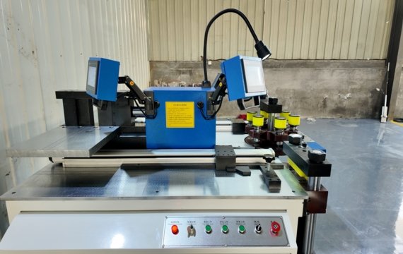
Busbars are crucial conductive structures in electrical cabinets and switchgear, responsible for connecting power input terminals to internal electrical components. For electrical cabinet OEMs, traditional manual processing methods are easily influenced by operator experience.
Busbar machines, by setting parameters, complete the busbar machining process, helping manufacturers control machining dimensions, connection hole positions, and bending angles. Compared to manual processing, CNC busbar machining equipment reduces repetitive adjustments. Precisely machined busbars optimize internal space layout and reduce wiring work.
Industrial Scope
| Application | Possible Busbar Role | Manufacturing Requirement |
|---|---|---|
| Switchgear | Main or distribution conductor | Drawing-controlled holes, bends and phase identification |
| Electrical Cabinets | Connections between incoming devices and internal components | Correct geometry and assembly sequence |
| Transformers | Terminal or internal conductor connection | Material, section, holes and bend geometry |
| Energy-Storage Equipment | Power connection between electrical components | Drawing revision, surface and part traceability |
| EV Charging Equipment | Internal power-distribution connection | Compact geometry and controlled connection features |
The application name alone does not determine the busbar section, manufacturing route or machine configuration. Use the approved project drawing and electrical specification.
Why Electrical Cabinet OEMs Upgrade to Busbar Machines?
| Production Condition | How a Machine May Help | What Must Still Be Verified |
|---|---|---|
| Repeated Finished Lengths | Uses a defined stop or positioning axis | Actual length, squareness and burr |
| Repeated Hole Patterns | Uses approved tooling and programmed coordinates where available | Hole size, position, pitch and edge distance |
| Repeated Bend Geometry | Reuses approved settings where supported | Released angle, bend line and overall dimensions |
| Frequent Model Changes | Stores or recalls defined programs where available | Correct revision, tooling and first approved part |
| Long or Heavy Raw Bars | Uses rollers, tables or feeding support | Operator count, alignment and safe handling |
| Mixed Production Batches | Combines several operations or programs | Changeover time and remaining manual tasks |
| Assembly Fit-Up Problems | Provides more controlled processing inputs | Drawing, datum, tooling and final inspection |
A busbar processing machine becomes valuable when the verified production constraint involves positioning, tooling, repeated operations, material handling or output. It should not be selected only because the factory produces electrical cabinets.
When Does a Cabinet Factory Need a Busbar Processing Machine?
Industrial switchgear systems withstand high current loads. Cable-based designs may create challenges in high-current applications because of complex routing, multiple connection points, and increased installation requirements.
Long-term operation of cable bundles under high current loads may increase heat accumulation and accelerate insulation aging.Busbars offer a high-current alternative.They replace the dispersed cable structure with metal conductive plates, ensuring current distribution and maintaining the safety of your cabinet operation.
OEM Assembly Pressure
Cable routing requires lengthy manual assembly. Increased orders can slow down the production line pace. In OEM production environments, manual cable routing depends heavily on operator experience. Different working methods may create variations between production batches and increase rework rates.Busbar machine can reduce the number of cable connections, simplify assembly procedures, and improve production consistency for OEM manufacturers.
Cabinet Space Limitation
Compact cabinet designs increase cabling congestion. High-density system designs often face space constraints. Increased components affect cable routing and encroach on internal equipment space.
Busbar machine can improve internal cabinet space utilization. By replacing multi-path cabling with a fixed conductive structure, they reduce wasted space, thus improving your overall design
How Busbar Manufacturing Affects Production Efficiency
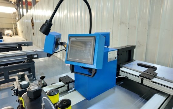
Busbar machining directly affects installation efficiency, assembly accuracy, and production consistency in electrical cabinet manufacturing.Each busbar manufacturing process directly affects final assembly accuracy, including cutting dimensions, hole positions, and bending angles.Busbar machining using real production line logic.
What Does a Busbar Processing Machine Produce?
| Operation | Machine Function | Finished-Part Verification |
|---|---|---|
| Shearing | Produces the required raw or finished length | Length, squareness, burr and end deformation |
| Punching | Produces holes and slots using approved tooling | Size, position, pitch, edge distance, burr and deformation |
| Bending | Forms flat, edge, offset or other approved geometry | Released angle, bend line, radius and overall dimensions |
| Forming | Produces approved embossing or special geometry where configured | Position, depth, shape and surface |
| Identification or Handling | Supports part flow where included | Correct project, cabinet, phase and status |
What Does CNC Control—and What Does It Not Control?
| Item | CNC or Servo May Control | It Does Not Automatically Confirm |
|---|---|---|
| Positioning Axis | Moves a defined stop, backgauge or feeder | Correct initial material alignment |
| Program Coordinates | Stores approved positions or parameters | Correct drawing revision |
| Bending Variable | Controls stroke, position or correction where configured | Finished released-angle tolerance |
| Program Recall | Retrieves a stored program | Correct tooling and material |
| Processing Sequence | Executes programmed steps where integrated | Automatic loading, rotation or inspection |
| Production Record | Stores selected values where available | Complete traceability or process capability |
CNC is a control method, not proof of complete automation or finished-part conformity. Confirm the controlled axes, remaining manual tasks and actual measured results.
Manual Limitation
Manual processing becomes difficult to maintain when OEM production requires higher output, repeatability, and consistent accuracy. Manufacturers may encounter issues including inconsistent dimensions, increased copper waste, and additional adjustment work. In the actual workshop, cutting, punching, and bending rely on manual judgment; different operating habits, deviations, and errors require secondary adjustments.
Small production volumes may tolerate manual processing, but larger OEM orders usually require higher repeatability and production consistency.But large-volume production creates rework pressure, slowing the production line.
CNC Busbar Processing Machine Upgrade for OEM Production
CNC busbar machines integrate cutting, punching, and bending through automatic CNC control, improving processing repeatability and reducing manual adjustment.The equipment uses programs to control the processing path, keeping the dimensions and hole positions of your busbars within set ranges. This controlled process improves dimensional consistency and makes production planning easier for OEM factories.
FAQ
What production challenges can busbar machines help solve?
Busbar machines can help electrical cabinet manufacturers improve hole positioning accuracy and reduce copper waste. Busbar machines are suitable for factories with OEM orders and strict delivery requirements.
Why do export-oriented electrical cabinet manufacturers prefer CNC busbar machines?
Export-oriented manufacturers require consistent processing quality. Production errors can affect inspection results, delivery schedules, and customer acceptance. CNC busbar machines can reduce the risks associated with international orders.
What thickness of copper busbar can a CNC busbar machining machine process?
The processing thickness depends on machine specifications, hydraulic capacity, tooling design, and customer requirements. Industrial CNC busbar machines are usually configured according to the copper thickness.
How many people are typically needed for a busbar processing line?
A standard OEM busbar processing line requires 2–4 people, depending on the level of automation of your equipment. Different types of equipment require different numbers of operators.
What size factory is suitable for different models of busbar equipment?
For small workshops, a semi-automatic busbar processing machine can be chosen, which allows for flexible production; CNC busbar processing machines are suitable for medium and large electrical cabinet manufacturers, as medium and large-sized manufacturers require high processing precision and stable production.
Final Thought
Busbar machine improve electrical cabinet manufacturing efficiency, consistency, and installation quality.
Fenghua provides CNC busbar cutting, punching, and bending machines for electrical cabinet manufacturers, switchgear OEMs, and power distribution equipment producers.