
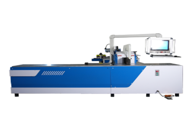
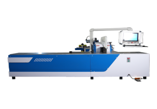
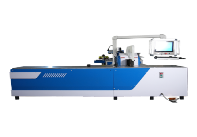
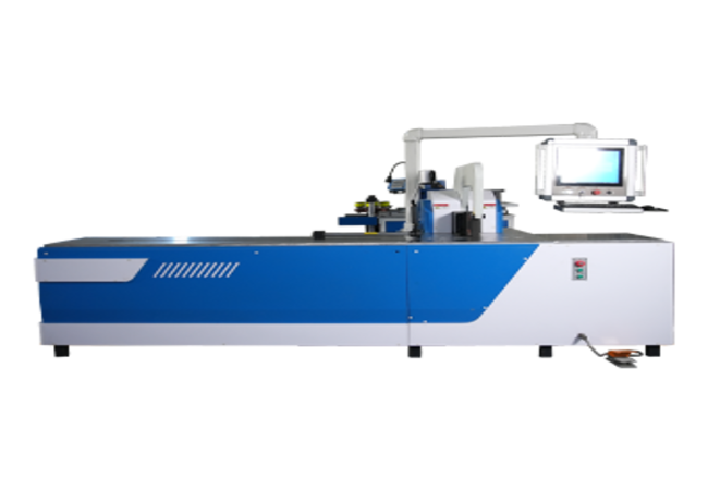
Hydraulic Busbar Bending Machine
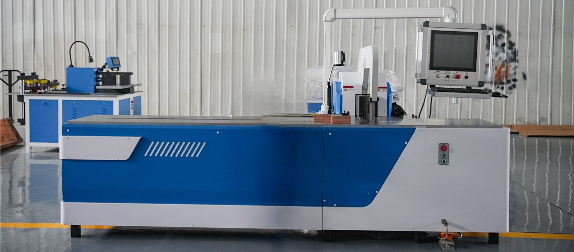
The Hydraulic Busbar Bending Machine is a dedicated machine for flat bending copper and aluminum busbars. Vertical or edge bending is available on confirmed machine models using dedicated tooling. Material loading remains manual on the listed models, while positioning and bending control depend on the selected machine configuration. The CNC Servo model uses PLC and servo-assisted positioning, while the Double-Head model is designed for simultaneous end forming in busduct production.
- Dedicated hydraulic bending for copper and aluminum busbars
- Flat bending supplied as the standard processing application
- Optional vertical, edge and offset bending with confirmed tooling
- Interchangeable tooling for different bending requirements
- Manual and servo-controlled configurations available for different requirements
- Suitable for customized drawings and small- to medium-batch production
- Technical Specifications
- Bending
- Busbar Bending Machine Selection Table
| Item | Specification |
| Product Type | Hydraulic Busbar Bending Machine |
| Machine Configuration | Single-Function, Manually Positioned Hydraulic Bending Machine |
| Processing Function | Hydraulic Busbar Bending |
| Processing Material | Copper and Aluminum Busbars |
| Standard Bending Application | Flat Bending |
| Optional Bending Applications | Vertical, Edge or Offset Bending with Confirmed Tooling |
| Busbar Width Range | See Model Selection Table |
| Busbar Thickness Range | See Model Selection Table |
| Feeding Method | Manual Loading |
| Positioning Method | Manual Positioning and Alignment |
| Hydraulic System Pressure | 31.5 MPa for the Stated Configuration |
| Hydraulic Drive | Hydraulic Cylinder Drive |
| Standard Control Method | Manual Control |
| Optional Control Method | PLC Control, Subject to Selected Model |
| Installed Power | See Model Selection Table |
| Power Supply | 380 V / 50 Hz / 3 Phase |
| Customized Voltage | Available Subject to Confirmed Electrical Configuration |
| Machine Dimensions | See Model Selection Table |
| Machine Net Weight | See Model Selection Table |
| Item | Specification |
| Rated Bending Force | See Model Selection Table |
| Standard Forming Method | Hydraulic Bending with Replaceable Tooling |
| Nominal Finished-Angle Range | 0–90°, Subject to Selected Model, Tooling and Material Springback |
| Standard Bending Type | Flat Bending |
| Vertical / Edge Bending | Optional, Subject to Confirmed Machine Structure, Material Dimensions and Dedicated Tooling |
| Offset / Z Bending | Optional with Dedicated Tooling and Drawing Review |
| Material Positioning | Manual Positioning |
| Tool Replacement | Manual Replacement of Interchangeable Tooling |
| Minimum Bend Radius | Confirmed According to Material, Thickness, Tooling Radius and Bend Geometry |
| Minimum Short-Leg Length | Confirmed According to Tooling Geometry, Material Thickness and Workpiece Access |
| Multiple-Bend Processing | Confirmed According to Part Geometry, Tooling Access and Processing Sequence |
| Model | Main Function | Processing Capacity | Recommended For |
| CNC Servo Busbar Bending Machine | Dedicated flat and vertical bending | Flat: 160 × 16 mm; Vertical: 120 × 12 mm | Customized copper and aluminum busbar bending |
| Double-Head Busbar Bending Machine | Simultaneous bending of both busbar ends | Confirmed according to busbar size and tooling | Busduct and busbar trunking production |
Final capacity must be confirmed against the customer’s material specification, dimensioned drawing and selected tooling.
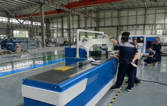
Interchangeable Tooling for Different Busbar Profiles
Different electrical products require different bending geometries. Instead of using one universal die, selected machine models can be configured with interchangeable tooling for different bend geometries.
Dedicated tooling may be evaluated for narrow-leg bends, large-radius bends, offset or Z bends and vertical bending. Feasibility depends on tooling access, busbar dimensions and part geometry.Tool selection should always be confirmed according to the finished drawing, material specification and required bending sequence.
Controlling Bend Radius and Springback
Achieving the required finished angle involves more than applying hydraulic force. Material properties influence the final angle after unloading, particularly when processing aluminum or high-conductivity copper.The machine is designed to work with appropriate bending tooling that controls deformation throughout the forming process.
Tooling radius and die geometry influence material deformation, inside radius and springback during forming. Final bending results depend on material yield strength, temper condition, bend radius, tooling geometry and the required finished angle.
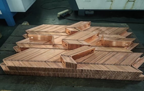
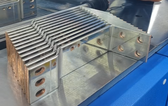
Busbar Components Supported with Confirmed Tooling
With suitable tooling, the machine can produce a wide variety of busbar configurations used in electrical equipment manufacturing, including:
- Standard L-shaped busbars
- Offset busbars
- Double-bend conductors
- Edge-bent busbars
- Short-leg busbars
- Multi-angle busbar components
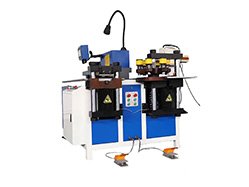
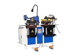
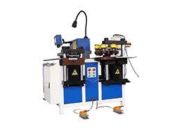
The machine is suitable for flat bending as standard and can also perform edge bending, offset bending and other special bending operations with compatible tooling. The available bending configuration depends on the selected tooling and machine model.
Tooling is selected according to the customer drawing, including material type, busbar dimensions, bend radius, leg length and finished angle. Customized tooling can be supplied for special applications.
No. The standard machine is manually operated and does not require CNC programming. Operators position the workpiece, install the required tooling and activate the hydraulic bending cycle.
Yes. The machine is designed for both copper and aluminum busbars. Final processing capability depends on material grade, thickness, temper condition and required bend geometry.
Yes. Special bending punches and dies can be designed according to customer drawings for non-standard busbar profiles, special bend radii or unique electrical component requirements. Capacity confirmation is recommended before production.

