
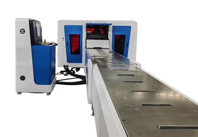
Busbar Cutting Machine
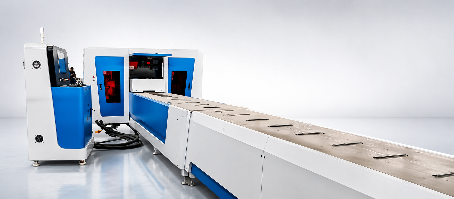
Fenghua supplies busbar cutting machines for cutting copper and aluminum busbars to specified lengths for switchgear, distribution cabinets, transformer connections and other electrical equipment. The machine configuration is selected according to busbar material, width × thickness, cutting length, required accuracy, production volume and downstream processing requirements.
- Copper and aluminum busbar cutting
- Cutting capacity configured according to busbar size
- Adjustable positioning for specified cutting lengths
- Cutting tooling selected according to conductor dimensions
- Available as dedicated equipment or integrated into busbar processing systems
- Technical Specifications
- Cutting Performance
- Machine Selection
The current GJBM series provides three integrated cutting, punching and bending configurations. The following values are model-level references for initial comparison.
| Parameter | GJBM303 | GJBM503 | GJBM803 |
| Overall Model Processing Reference (W × T) | 160 × 16 mm | 260 × 16 mm | 300 × 20 mm |
| Cutting Force | 350 kN | 500 kN | 800 kN |
| Motor Power | 3 × 4 kW | 3 × 5.5 kW | 3 × 7.5 kW |
| Power Supply | 380 V | 380 V | 380 V |
| Machine Dimensions | 1,780 × 1,400 × 1,400 mm | 1,800 × 1,500 × 1,300 mm | 1,950 × 1,550 × 1,200 mm |
| Machine Weight | Approx. 1,300 kg | Approx. 1,800 kg | Approx. 2,300 kg |
| Processing Functions | Punching / Bending / Cutting | Punching / Bending / Cutting | Punching / Bending / Cutting |
| Applicable Materials | Copper / Aluminum | Copper / Aluminum | Copper / Aluminum |
The published width × thickness values are overall model-level processing references. Confirm the maximum cutting width and thickness separately for the cutting station, actual conductor material and blade configuration.
Busbar cutting performance should be evaluated from measured finished parts rather than nominal cutting force alone.
| Inspection Item | Buyer Verification |
| Finished Length | Compare required and measured cut length |
| Cut Squareness | Inspect end-face perpendicularity against the drawing requirement |
| Burr Condition | Record the permitted and measured burr condition |
| End Deformation | Check distortion at the cut end |
| Surface Condition | Inspect scratches, pressure marks and coating damage |
| Repeatability | Measure multiple consecutive parts rather than one selected sample |
| Tooling Condition | Confirm blade condition, clearance and replacement requirements |
| Complete Cycle | Record loading, positioning, cutting, unloading and inspection time |
Representative copper or aluminum busbars should be tested during FAT. The drawing datum, measuring instrument, sample quantity and acceptance criteria should be agreed before the test.
| Production Requirement | Starting Configuration | Published Reference | Buyer Must Confirm |
| Compact integrated processing | GJBM303 | 350 kN; overall 160 × 16 mm reference | Cutting-station capacity, material and blade |
| Medium-capacity integrated processing | GJBM503 | 500 kN; overall 260 × 16 mm reference | Material-specific capacity and cut quality |
| Larger-section integrated processing | GJBM803 | 800 kN; overall 300 × 20 mm reference | Maximum proposed material, handling and FAT |
| Specific finished lengths or positioning | Custom Cutting Configuration | Drawing-based configuration | Positioning range, support, tolerance and tooling |
The model name or nominal cutting force alone does not confirm suitability. Select the configuration according to the actual material, finished drawing and production workflow.
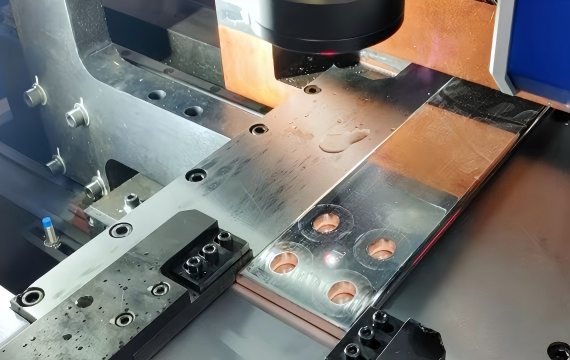
Busbar Cutting Quality
Cutting quality should be evaluated from the finished busbar rather than nominal cutting force alone. During FAT, verify finished length, cut squareness, burr condition, end deformation and visible surface damage using multiple consecutive samples. Finished-length accuracy should also be evaluated separately from positioning accuracy under the agreed inspection method.
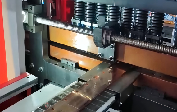
Cutting Tooling and Configuration
Cutting tooling should be selected according to conductor material, width × thickness and required cut condition. The quotation should confirm blade configuration, cutting clearance and replacement method. For long or heavy busbars, material support, positioning range and handling method should also be reviewed before the final machine configuration is approved.
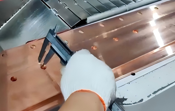
Copper and Aluminum Busbar Cutting
Fenghua cutting configurations can be evaluated for both copper and aluminum busbars. Material grade or alloy, temper, width and thickness should be confirmed because different conductors may require different cutting-force margins, blade clearance and support conditions. Surface-sensitive busbars should also be inspected for scratches, pressure marks and visible damage during FAT.
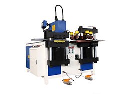
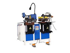
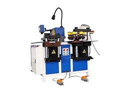
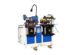
The published overall width × thickness value is a model-level processing reference. Maximum cutting width and thickness should be confirmed separately for the cutting station, actual conductor material and blade configuration.
Suitable configurations can process both materials, but the copper grade or aluminum alloy, temper, width, thickness, blade clearance and required finished quality should be confirmed separately.
No. Positioning controls the material reference before cutting. Finished length can also be affected by clamping, material movement, support, blade condition, deformation and the measurement method.
FAT should verify the proposed material and section, required and measured finished length, cut squareness, burr condition, end deformation, surface condition and results from multiple consecutive samples.
A dedicated cutting configuration is more suitable when cutting and length positioning are the primary requirements. A 3-in-1 machine is more suitable when punching, cutting and bending are regularly required within the same production area. Each processing station should still be verified separately.

