
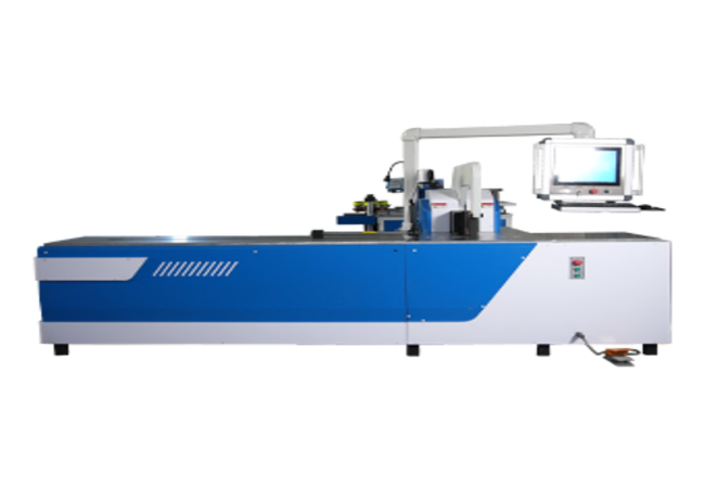
PLC Parameter Setting and Servo Positioning for Copper and Aluminum Busbars
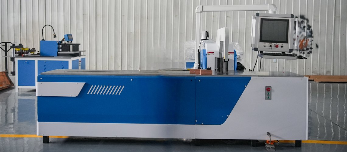
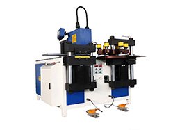
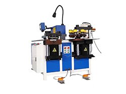
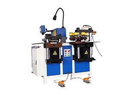
The Fenghua Automatic Busbar Bending Machine is a CNC-controlled forming machine for copper and aluminum busbars used in switchgear, electrical cabinets, transformers and power distribution equipment. The machine provides a nominal bending force of 400 kN, with a maximum flat-bending capacity of 160 × 16 mm and a maximum vertical-bending capacity of 120 × 12 mm.
- Nominal bending force of 400 kN
- Flat-bending capacity up to 160 × 16 mm
- Vertical-bending capacity up to 120 × 12 mm
- PLC/CNC parameter setting with servo backgauge positioning
- Bending-angle accuracy of ±0.3° under agreed FAT conditions
- Backgauge positioning accuracy of ±0.15 mm
- Replaceable tooling for flat, vertical and special profiles
- Automatic Busbar Bending Machine Selection
- Automatic Busbar Bending Machine Specifications
| Configuration | Main Function | Processing Capacity | Control System | Recommended Applications |
| 400 kN CNC Servo Positioning Configuration | Digital position setting with flat and vertical bending | Flat: up to 160 × 16 mm; Vertical: up to 120 × 12 mm | PLC/CNC Control with Servo Backgauge | Switchgear, electrical cabinet and transformer busbar production |
| Optional Program Memory Configuration | Storage and recall of confirmed positioning and process parameters | Same mechanical capacity as the approved machine configuration | PLC/CNC Controller with Confirmed Program Functions | Repeat orders and recurring finished-part drawings |
| Customized Tooling and Control Configuration | Special profiles, tooling and optional control functions | Confirmed according to material specification and drawing | Customized Controller and Tooling Configuration | Non-standard busbar components and special bending projects |
The program-memory configuration is only available when supported by the selected controller and listed in the technical quotation.
Published capacities do not apply to every material grade, temper, bend radius or finished geometry. Final machine selection must be confirmed using the customer’s material specification, dimensioned drawing and selected tooling.
| Item | Specification |
| Product Type | Automatic CNC Busbar Bending Machine |
| Processing Material | Copper and Aluminum Busbars |
| Nominal Bending Force | 400 kN |
| Maximum Flat-Bending Capacity | 160 × 16 mm |
| Maximum Vertical-Bending Capacity | 120 × 12 mm |
| Bending-Angle Accuracy | ±0.3° |
| Backgauge Positioning Accuracy | ±0.15 mm |
| Spindle Travel | 210 mm |
| Backgauge Length | 1,500 mm |
| Positioning Servo Motor Power | 750 W |
| Main Motor Power | 5.5 kW |
| Control System | PLC/CNC Control with Servo Backgauge |
| Bending Operation | Servo Positioning with Operator-Initiated Hydraulic Bending |
| Material Loading | Manual |
| Workpiece Support | Manual or with External Support Equipment |
| Tool Replacement | Manual |
| Bending Drive | Hydraulic |
| Power Supply | 380 V / 50 Hz / 3 Phase |
| Customized Voltage | Available with Confirmed Electrical Configuration |
| Machine Dimensions | 3,450 × 1,200 × 1,750 mm |
| Machine Net Weight | Approximately 3,350 kg |
The maximum processing capacity does not apply to every copper or aluminum grade, material temper, bend radius or finished geometry.Final capacity must be confirmed against the material grade or alloy, temper, busbar dimensions, inside bend radius, minimum short-leg length, tooling clearance and bending sequence.
The stated ±0.3° and ±0.15 mm values should be verified under agreed FAT conditions. Backgauge positioning accuracy must not be interpreted as universal finished-part dimensional accuracy.
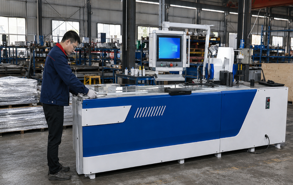
CNC Programming for Repeated Bending Accuracy
When the confirmed controller includes program-memory functions, approved positioning values and production parameters can be stored and recalled for repeat orders.
Typical production benefits include:
- Digital positioning-value entry
- Reuse of confirmed positioning settings
- Reduced mechanical-stop adjustment
- Easier setup for recurring drawings
- Consistent positioning references for repeat batches
- Faster changes between approved busbar specifications
The stated ±0.15 mm value applies to servo backgauge positioning. The stated ±0.3° value should be evaluated using an agreed material, tooling radius, target angle, sample quantity and inspection method.
Flexible Tooling for Different Busbar Configurations
Replaceable tooling allows the machine to be evaluated for different busbar dimensions, bending radii and finished profiles.
Each application must be reviewed against:
- Material grade or alloy and temper
- Busbar width and thickness
- Inside bend radius
- Minimum short-leg length
- Distance between bends
- Tooling clearance
- Frame interference
- Workpiece turning space
- Required bending sequence
Different profiles may require standard, optional or customized tooling. The quotation should identify every included tool, tooling radius, quantity, installation accessory and replacement lead time.
A published maximum busbar size does not mean that every bending profile can be produced at the maximum width and thickness.
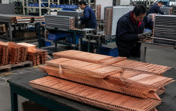
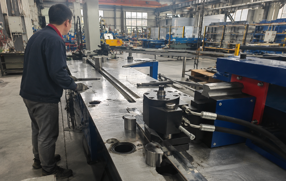
Designed for Modern Busbar Fabrication
The Automatic Busbar Bending Machine is suitable for:
- Switchgear busbar production
- Electrical distribution cabinets
- Low-voltage control panels
- High-voltage electrical equipment
- Transformer connecting busbars
- Power distribution assemblies
- Energy storage electrical equipment
- Solar power distribution systems
- Customized copper and aluminum busbar components
- Repeated U-shaped and Z-shaped parts with confirmed tooling
This configuration is suitable when your production requires changing positioning values, recurring finished-part drawings, repeated bending locations, mixed production batches and digital production settings. Medium- or high-volume capability should be evaluated using complete cycle time, operator count and conforming parts per shift rather than hydraulic bending speed alone.
Yes. Copper and aluminum must be evaluated separately according to the material grade or alloy, temper, width, thickness, tooling and required bending geometry.
The confirmed standard automatic functions include digital position setting and servo backgauge movement. Program storage and parameter recall depend on the selected controller. Material loading, support and final alignment remain manual.
No. Automatic longitudinal feeding is not included in the standard configuration. It must be specified as a separate material-feeding system.
The maximum flat-bending capacity is 160 × 16 mm. Applicable capacity depends on the material grade or alloy, temper, inside bend radius, tooling and finished geometry.
The maximum vertical-bending capacity is 120 × 12 mm with the applicable tooling. Final feasibility must be confirmed against the material specification and drawing.

