
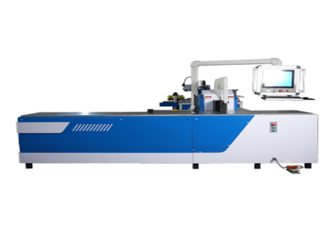
CNC Busbar Bending Machine
The Fenghua CNC Busbar Bending Machine is a dedicated forming machine for copper and aluminum busbars. The operator enters the required positioning value through the PLC interface, while the servo-assisted backgauge moves to the specified bending-position reference.
- Nominal bending force of 400 kN
- Maximum flat-bending capacity up to 160 × 16 mm
- PLC-set servo-assisted backgauge positioning
- Nominal bending-angle accuracy of ±0.3° under agreed test conditions
- Backgauge positioning accuracy of ±0.15 mm
- Replaceable tooling for flat, vertical and customized bending profiles
- CNC Busbar Bending Machine Specifications
- Control and Automation Scope
| Item | Specification |
| Product Type | CNC Servo Busbar Bending Machine |
| Processing Material | Copper and Aluminum Busbars |
| Nominal Bending Force | 400 kN |
| Maximum Flat-Bending Capacity | 160 × 16 mm |
| Maximum Vertical-Bending Capacity | 120 × 12 mm, Subject to Engineering Confirmation |
| Nominal Bending-Angle Accuracy | ±0.3°, Subject to Agreed FAT Conditions |
| Backgauge Positioning Accuracy | ±0.15 mm, Subject to Factory Verification |
| Spindle Travel | 210 mm |
| Backgauge Length | 1,500 mm |
| Positioning Servo Motor Power | 750 W, Subject to Electrical BOM Confirmation |
| Main Motor Power | 5.5 kW |
| Control System | PLC with Servo-Assisted Positioning |
| Material Loading | Manual |
| Bending Drive | Hydraulic |
| Machine Dimensions | 3,450 × 1,200 × 1,750 mm |
| Machine Net Weight | Approximately 3,350 kg |
The maximum processing capacity does not apply to every material grade, temper, bend radius or finished geometry. Final capacity must be confirmed against the customer’s material specification, dimensioned drawing, minimum short-leg length and selected tooling.
The stated accuracy values should be evaluated under agreed FAT conditions, including the test material, busbar dimensions, tooling, sample quantity, measuring instrument and acceptance tolerance.
| Function | Standard Scope |
| Position Value Setting | Entered through the PLC interface |
| Backgauge Positioning | Servo-driven movement to the set reference |
| Material Loading | Manual |
| Workpiece Support | Manual or with external support equipment |
| Final Alignment | Manual |
| Flat Bending | Available with the applicable tooling |
| Vertical Bending | Available with the applicable tooling |
| Bending Cycle | Started by the operator |
| First-Part Inspection | Completed by the operator or quality inspector |
| Tool Replacement | Manual |
| Automatic Material Feeding | Not included in the standard configuration |
| Automatic Tool Change | Not included in the standard configuration |
Program storage, drawing import, network connection and production-scheduling functions should only be included when they are specified in the approved controller configuration and technical quotation.
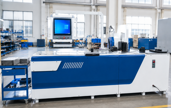
Servo Backgauge Positioning for Repeated Production
With the CNC servo configuration, the required position is entered digitally through the control interface. The servo-driven backgauge moves to the specified reference value, reducing repeated manual stop adjustment when producing parts with the same bending location.
This configuration is suitable for:
- Repeated bending locations
- Frequently changing busbar dimensions
- Mixed small- and medium-batch orders
- Customized finished-part drawings
- Flat and vertical bending requirements
- Production requiring digital positioning references
The servo positioning system does not eliminate the need for correct material support, tooling selection, final alignment, first-part inspection or springback adjustment.
Supported Busbar Bending Profiles
Depending on the selected tooling and finished-part geometry, the machine can be evaluated for:
- Standard 90° flat bends
- Variable-angle flat bends
- Vertical or edge bends
- Offset bends
- Z-shaped busbars
- Narrow-leg bends
- Large-radius bends
- Double-bend components
- Sequential multiple-bend parts
Each profile must be reviewed against material dimensions, tooling interference, short-leg length, bending sequence and workpiece access. A published maximum material size does not mean that every profile can be produced at that maximum width and thickness.
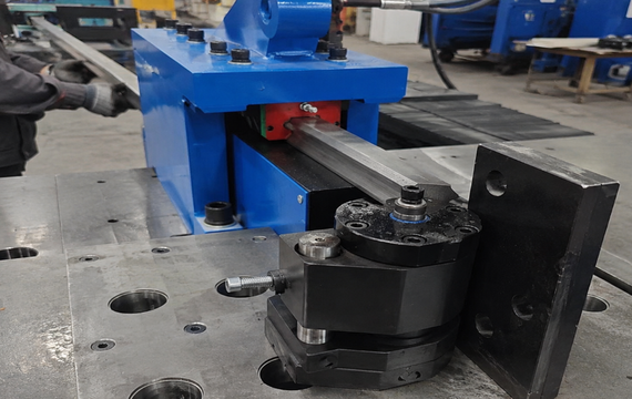
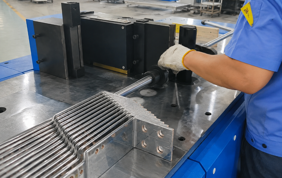
CNC Servo vs Manual-Positioning Busbar Bending
A manual-positioning bending machine is better suited to low-volume customized work where operators set each bending location using mechanical stops or manual measurement. A CNC servo busbar bending machine uses PLC-set backgauge positioning, making it more suitable for repeat orders, changing dimensions and mixed-batch production. Both configurations still require manual loading, alignment, tooling changes and first-part inspection. Choose according to your drawing mix, batch size, positioning requirements and acceptable setup time.
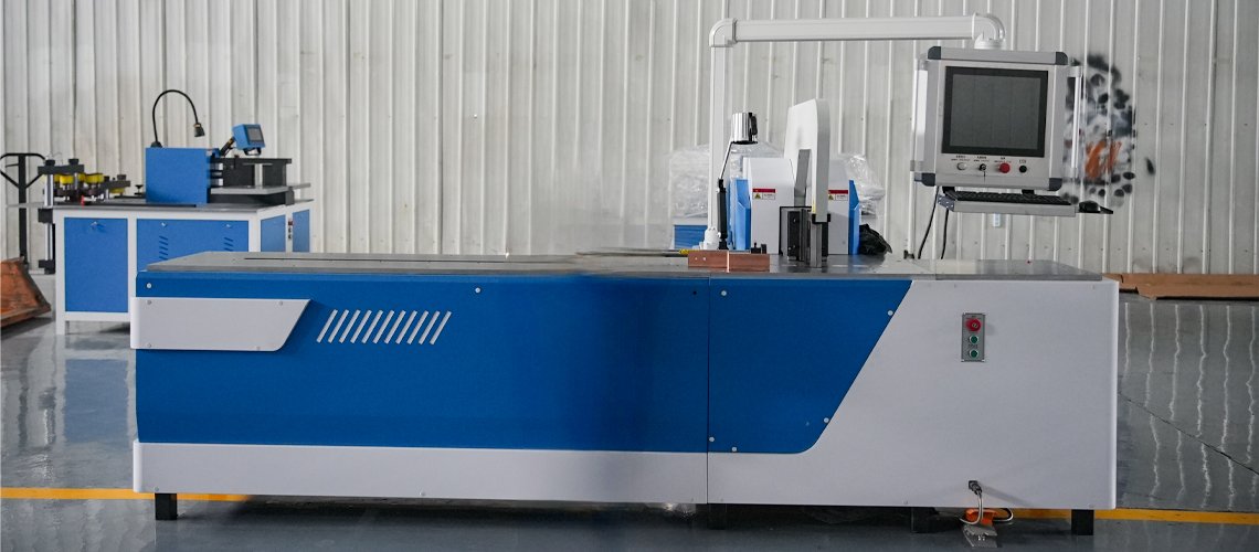
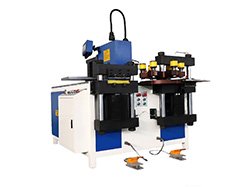
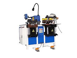
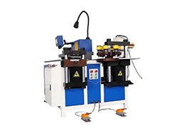
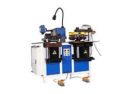
The operator enters the required positioning value through the PLC interface. The servo system moves the backgauge to the specified bending-position reference. Material loading, support and final alignment remain manual.
The maximum flat-bending capacity is 160 × 16 mm. The applicable capacity depends on the material grade or alloy, temper, tooling radius, bend geometry and minimum short-leg length.
The maximum vertical-bending capacity is 120 × 12 mm with the applicable vertical-bending tooling. Final feasibility must be confirmed against the material specification and drawing.
Yes. The machine is designed for copper and aluminum busbars. Each material must be evaluated according to its grade or alloy, temper, dimensions and required bend geometry.
No. The operator manually loads, supports and aligns the busbar. The servo system automatically moves the backgauge to the position entered through the PLC interface.

